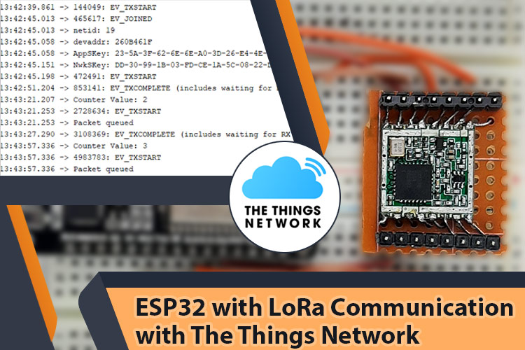
When we are talking about LoRa, it's been more than 10 years since its first official launch and since that day LoRa is getting increasingly popular day by day. With so many IoT devices available, this low-power long-range wireless communication could fit into a plethora of applications. It is expected that by 2025 we will have 29 Billion devices connected to the internet. To give you an idea that is more than four times the population of earth today.
So in this tutorial, we have decided to set up the popular HDPA13A which is a SX1276 LoRa end Node with ESP32, and send data to the TTN network, and to do so we will be using the RG186 LoRa Gateway which we had already learned to set up in one of our previous projects. We will also be setting up the popular SX1276, 868MHz LoRa end node module that we will configure to work with INDIA’s Standards. Finally, we will be discussing the problems we have faced and the solutions we found to establish communication with The Things Network. So without further ado, let's get right into it.
SX1276 LoRa Module Pinout
The pinout of the SX1276-based LoRa module is shown below. For this tutorial, we will be using the HDP13A V1.1 LoRa Module which is designed and developed by HPDTeK a well-known manufacturer in china. The pinout of the module is shown below-
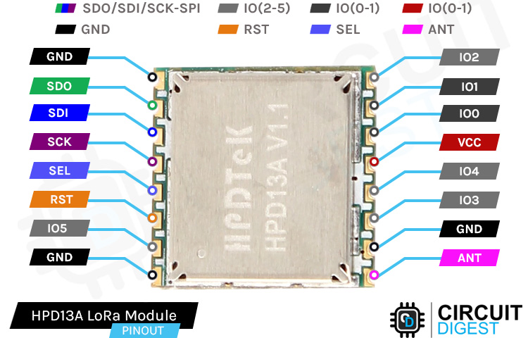
GND This is the Ground Pin of the module that should be connected to the Ground pin of the ESP32 or Arduino whichever microcontroller you are using. There are a total of three ground pins on the board, all those are connected internally.
SDO(MISO) The SDO pin is the Serial Data Out pin of the Microcontroller. An output signal on a device where data is sent out to another SPI device.
SDI(MOSI) The SDI pin is the Serial Data In for the Microcontroller. An input signal on a device where data is received from another SPI device.
SCK is the Serial Clock Pin of the Module. The Serial Clock is generated by the microcontroller.
SEL Sel is the Chip Select pin of the Module, activated by the controller to initiate communication with a given peripheral.
RST This is the Reset pin of the module board which is used to reset the microcontroller to its initial values
IO2-5 These are the GPIO pins of the LoRa module. These can be set to High or Low in Software.
ANT This is the pin where the Antenna needs to be attached. You need to connect a proper antenna according to the datasheet.
VCC This is the power pin of the module, you can connect this to the VCC pin to any 3.3V pin. As the max voltage level of the module is 3.3V.
SX1276 886 MHZ LoRa Module
For this tutorial, we will be using the 868MHZ LoRa module which is designed and manufactured by SEMTECH. The module is a very easy-to-use, low-cost, high-efficiency module that can be used in many different applications.
The SX1276/77/78/79 transceivers feature the LoRaTM long-range modem that provides ultra-long range spread spectrum communication and high interference immunity whilst minimizing current consumption. It's said that by using SX1276 one can achieve a sensitivity of over -148dBm using a low-cost crystal and bill of materials.
What is the Difference Between HPD13A SX1276 and RFM95W Lora Module?
As you can see from the above image the name of the module is shown as the HPD13A module and the listing in the distributor’s website said it was SX1276 LoRa module. This was very confusing at first.
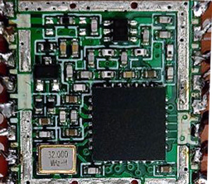
So, we decided to decap the module to see what's underneath. And from the above image you can see we found out that the company named HPDTek assembled the module so they are using their own part number and under the hood you can see it's made out of the SX1276 LoRa IC.
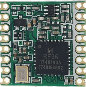
Now the question remains what is the difference between the RFM95W and the SX1276 IC. The modules are the same so the characteristics of the modules are also the same. If your objective is to establish LoRa communication this is not that hard to do. HopeRF licenses the technology from Semtech. So, the unshielded RFM95W module is virtually identical to some of the SX127x modules and its pin- and software are also compatible. In the above image, you can see the difference between two modules.
Making Breakout Board with Perfboard
If you check the pin pitch of the module, it's not breadboarded friendly so we need to make a breakout board for the module, there are two ways to do so. You can make a breakout board by soldering the module in a perf board and soldering some header pins to it. The second way is to make a PCB for the model and solder the module to the PCB. For our case, we have selected the first method as it is simple and takes very little time. The complete construction of the breakout board is shown below.
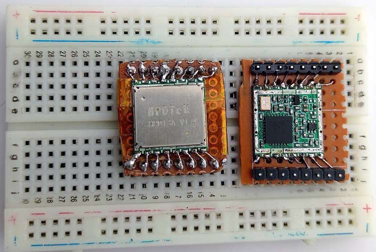
If you check out the HPD13A module it comes with a metal shield cap to reduce EMI and interference. We have removed the cap to see the internal construction of the module as you can see in the above picture. We did this because it will give us a good idea of what is inside the module.
SX1276 with ESP32 Circuit Diagram
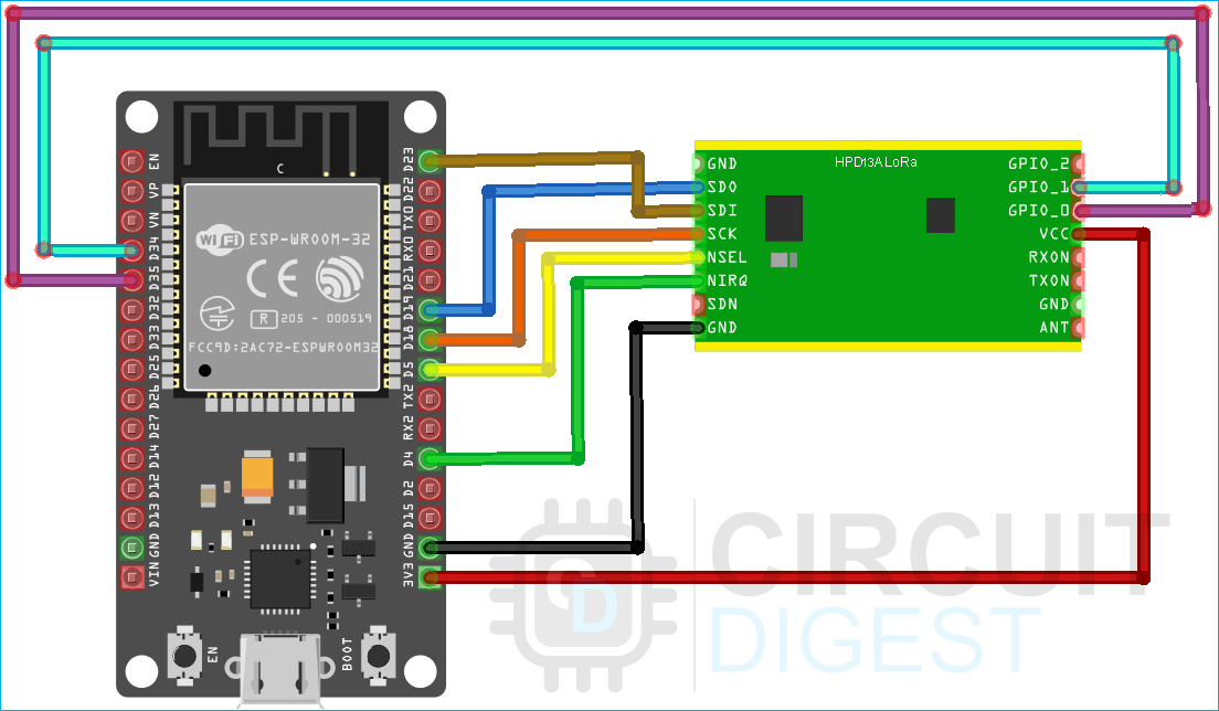
The schematic diagram of the SX1276 module with ESP32 is simple and straightforward. The complete schematic diagram is shown below.
As we have mentioned earlier the HX1276 module contains 16 pins, 8 on both sides. Out of those 16 pins, three are ground pins, there is a 3.3V tolerant VCC pin and others are SPI pins. Now we need to connect the SPI pins of the LoRa module to the SPI pins of the ESP32 as shown in the above image. You can use the table down below to make sure that all the connections are done correctly.
|
HPD13A LoRa SX1276 Module |
ESP32-WROOM Dev Module V1 |
|
3.3V |
3.3V |
|
GND |
GND |
|
SCK |
D18 (SCLK) |
|
SDI(MOSI) |
D23 (MOSI) |
|
SDO(MISO) |
D19 (MISO) |
|
SEL(CS) |
D26 (User Defined) |
|
RST |
D25 (User Defined) |
|
IO0 |
D23 (User Defined) |
|
IO1 |
D22 (User Defined) |
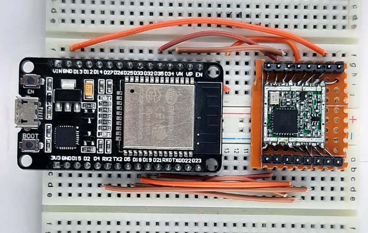
We have used breadboard jumper wires to connect the HPD13A module with the ESP32. The hardware circuit is shown below.
TTN ABP vs OTAA Activation Methode
Every end device must be registered with a network before sending and receiving messages. This procedure is known as activation. There are two activation methods available:
- Over-The-Air-Activation (OTAA) - The most secure and recommended activation method for end devices. Devices perform a join procedure with the network, during which a dynamic device address is assigned and security keys are negotiated with the device.
- Activation By Personalization (ABP) - requires hardcoding the device address as well as the security keys in the device. ABP is less secure than OTAA and also has the downside that devices can not switch network providers without manually changing keys in the device.
The join procedure for LoRaWAN 1.0.x and 1.1 is slightly different. The following two sections describe the join procedure for LoRaWAN 1.0.x and 1.1 separately.
If you want to learn more about the Device Activation Process on TTN, you can follow the linked documentation on the TTN website.
Setting up the End Nodes on the TTN Network
To transmit data to the TTN network, you need to first set up your gateway, and once that is done you need to set up your end nodes properly in order for the device to work properly. For that, you need to make a TTN account or log in to your existing TTN account. Once you have successfully logged in you need to go enter the TTN Console. If you have done everything correctly, you will be presented with the screen shown in the image below-
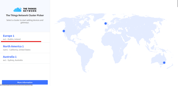
Once we are here we need to select a cluster, if you want to know more about the cluster you can click on the more information button. For our case, we will choose europe1.
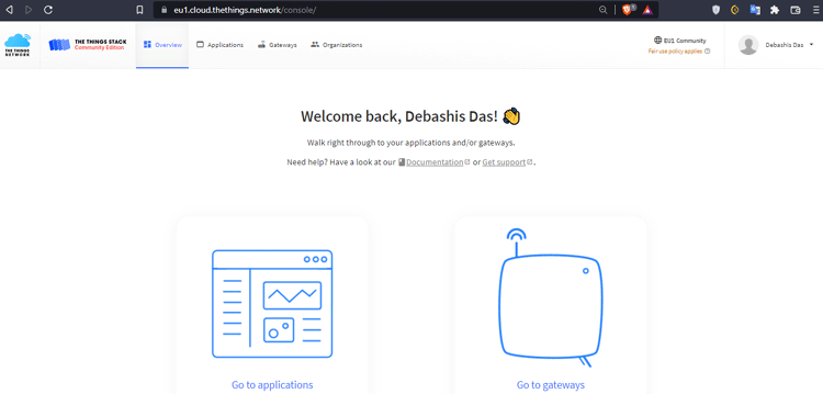
Once you do this you will be presented with the screen that is shown above. Now click on “Go to application”.
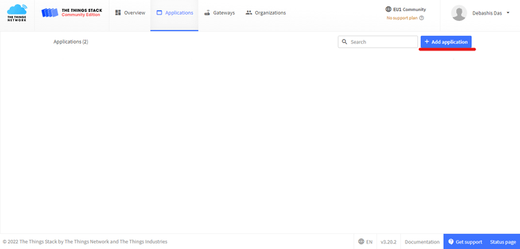
You will be presented with the screen shown above, here you need to click on the Add application button to create your first application.
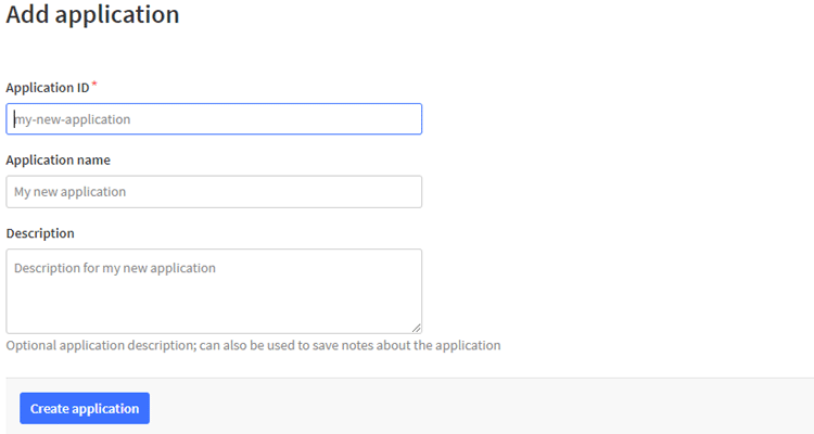
Now you need to create a new application by providing it with a unique Application ID and name. Once that is done the Description part is optional and you can click on the create application button.

Once done, you will be presented with the screen that is shown above, now you need to create End Nodes for your application, as mentioned earlier, end nodes are the devices that send data to the application server.
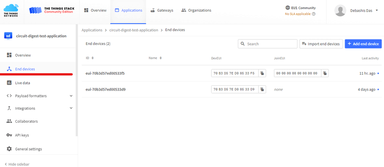
Now click on the newly created Application and click on the end node button on the left and click on add application button on the right. As you can see from this demonstration we have already created two end nodes. One is to test the ABP method and the other one is to test the OTAA method.
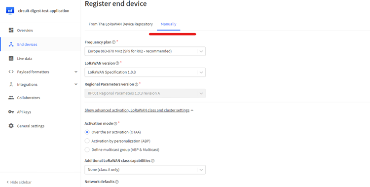
Now once you click on the add end node button, you will be presented with the screen that is shown above. Now click on it manually and follow along. First, we select the frequency plan, the LoRaWAN Specification, and the Activation Mode and for our first example, we are configuring it as OTAA.
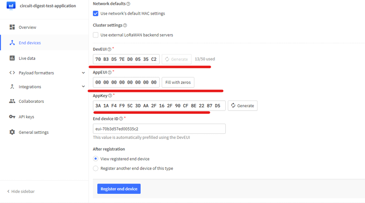
Next, all you need to do is generate the keys for your end nodes and you are all done. Now click on the Register end device button to complete the process. Please keep in mind that your DeviceEUI, AppKey, and AppEUI are the three most important keys that you need to be careful with. Now in the next section, we will know how you can create an application with the ABP activation method. The process is very similar. All you need to do is in the activation mode section you need to set the activity mode as ABP and generate the keys accordingly.
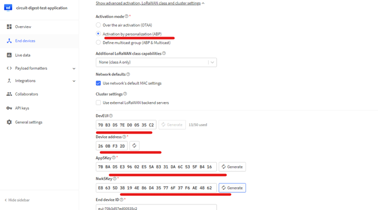
Now in the above image, you can see that we have selected the ABP activation method and we have generated the Device Address, the NwSKey, and the AppSKey, the Device EUI will be auto-generated. Now all that is done, you can click on the Register end device button to complete the process.
Now we are all set on the TTN side and finally move on to the coding part.
Arduino Code to Interface SX1276 Module with ESP32
The code for interfacing the HPD13A SX1276 Based Lora module is very simple and easy to understand. All we need to do is download the arduino-lmic library by mcci-catena and use its example code to communicate with the SX1276 module. But before we can use the example code in the library, we need to first configure it so that it can work with HX1276 with 868MHz frequency,
// project-specific definitions
// project-specific definitions
#define CFG_eu868 1
//#define CFG_us915 1
//#define CFG_au915 1
//#define CFG_as923 1
// #define LMIC_COUNTRY_CODE LMIC_COUNTRY_CODE_JP /* for as923-JP; also define CFG_as923 */
//#define CFG_kr920 1
//#define CFG_in866 1
#define CFG_sx1276_radio 1
To do so we need to change the project configuration that is shown above, you can find this project configuration inside the arduino-lmic library inside your Documents Arduino Library. Once that is done, we can open up the TTN-OTAA example sketch to the ESP32. But before doing so we need to paste in our keys in order to talk to the TTN.
Open up the example sketch TTN-OTAA by going to File > Examples > MCCI LoRaWAN LMIC Library > ttn-otaa
// This EUI must be in little-endian format, so least-significant-byte
// first. When copying an EUI from ttnctl output, this means to reverse
// the bytes. For TTN issued EUIs the last bytes should be 0xD5, 0xB3,
// 0x70.
static const u1_t PROGMEM APPEUI[8] = { 0x00, 0x00, 0x00, 0x00, 0x00, 0x00, 0x00, 0x00 };
void os_getArtEui (u1_t* buf) {
  memcpy_P(buf, APPEUI, 8);
}
// This should also be in little endian format, see above.
static const u1_t PROGMEM DEVEUI[8] = { 0xFF, 0x43, 0x45, 0xD0, 0xDE, 0xD5, 0xB3, 0x70 };
void os_getDevEui (u1_t* buf) {
  memcpy_P(buf, DEVEUI, 8);
}
// This key should be in big endian format (or, since it is not really a
// number but a block of memory, endianness does not really apply). In
// practice, a key taken from ttnctl can be copied as-is.
static const u1_t PROGMEM APPKEY[16] = { 0xBB, 0xAB, 0xAA, 0xD6, 0x47, 0x5A, 0xAC, 0xBC, 0x36, 0xAC, 0x22, 0x4A, 0xF2, 0x78, 0x33, 0x72 };
Now if you look at the code carefully you will find placeholders for the keys that we copied earlier. Paste in our keys according to MSB or LSB format. If you check out the comments above you can see which is which.
Now we need to set up the pins for the module, inside the code you will see a structure that is shown below-
const lmic_pinmap lmic_pins = {
  .nss = 5,
  .rxtx = LMIC_UNUSED_PIN,
  .rst = 4,
  .dio = {34, 35, LMIC_UNUSED_PIN},
};
In this structure, you need to set the nss, rst IO0, and IO1 pins in order for the module to work properly. Now we are all set and we can upload the example code to the ESP32, that's all you have to do for the TTN-OTAA example; now let's see how the TTN-ABP example works.
// LoRaWAN NwkSKey, network session key
// This should be in big-endian (aka msb).
static const PROGMEM u1_t NWKSKEY[16] = { 0xE8, 0x72, 0x48, 0x5E, 0x58, 0x57, 0xFF, 0xDB, 0xFA, 0x57, 0x0B, 0x18, 0x95, 0x04, 0x90, 0x21 };
// LoRaWAN AppSKey, application session key
// This should also be in big-endian (aka msb).
static const u1_t PROGMEM APPSKEY[16] = { 0x44, 0x29, 0x95, 0xC5, 0x13, 0xDB, 0x7C, 0xE0, 0xEB, 0x8C, 0x41, 0x07, 0x56, 0x41, 0x82, 0xC8 };
// LoRaWAN end-device address (DevAddr)
// See http://thethingsnetwork.org/wiki/AddressSpace
// The library converts the address to network byte order as needed, so this should be in big-endian (aka msb) too.
static const u4_t DEVADDR = 0x260B9869 ; // <-- Change this address for every node!
const lmic_pinmap lmic_pins = {
  .nss = 5,
  .rxtx = LMIC_UNUSED_PIN,
  .rst = 4,
  .dio = {34, 35, LMIC_UNUSED_PIN},
};
For the TTN-ABP example, the code is practically the same; the only changes you need to make is that you need to put in the DEVADDR(Device Address), APPSKEY(App Session Key), and NWKSKEY(Network Session Key) and you can upload the code. Complete example code can be found at the bottom of the document.
Testing ABP based LoRaWAN Node
Once the code is uploaded, we can open up the serial monitor to check if the module is working properly or not.
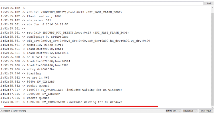
And as you can see from the output data on the serial monitor window, we are getting continuous transmission, and on the TTN Side, we are receiving our payload.

The Hex value is 48656C6C6F2C20776F726C6421 if you convert the HEX to text you can get the message.
Testing the OTAA Based LoraWan Node
Now we upload the OTAA-based code and open up the serial monitor window. You can see a lot of messages and the Keys which means the device was able to successfully join TTN.

On the TTN side it looks something like the image shown below.

And in the above image, you can see the message in text format.
Working of the SX1276 LoRa module
To test the circuit we have made a very small change in the code and added a counter, this counter will increment once every second and send the counter data to the TTN network. In the GIF shown below you can see that we have powered up the module and its sending the data to TTN. We can verify that by putting the TTN window and the Serial Monitor window side by side.
This is the end of the tutorial, if you have any doubts or issues, please feel free to comment below. Also, you can use our forum to start the conversation with our engineers.
Below you can find all the required files.
TTN-OTAA Code
/*******************************************************************************
Copyright (c) 2015 Thomas Telkamp and Matthijs Kooijman
Copyright (c) 2018 Terry Moore, MCCI
Permission is hereby granted, free of charge, to anyone
obtaining a copy of this document and accompanying files,
to do whatever they want with them without any restriction,
including, but not limited to, copying, modification and redistribution.
NO WARRANTY OF ANY KIND IS PROVIDED.
This example sends a valid LoRaWAN packet with payload "Hello,
world!", using frequency and encryption settings matching those of
The Things Network.
This uses OTAA (Over-the-air activation), where where a DevEUI and
application key is configured, which are used in an over-the-air
activation procedure where a DevAddr and session keys are
assigned/generated for use with all further communication.
Note: LoRaWAN per sub-band duty-cycle limitation is enforced (1% in
g1, 0.1% in g2), but not the TTN fair usage policy (which is probably
violated by this sketch when left running for longer)!
To use this sketch, first register your application and device with
the things network, to set or generate an AppEUI, DevEUI and AppKey.
Multiple devices can use the same AppEUI, but each device has its own
DevEUI and AppKey.
Do not forget to define the radio type correctly in
arduino-lmic/project_config/lmic_project_config.h or from your BOARDS.txt.
*******************************************************************************/
#include <lmic.h>
#include <hal/hal.h>
#include <SPI.h>
//
// For normal use, we require that you edit the sketch to replace FILLMEIN
// with values assigned by the TTN console. However, for regression tests,
// we want to be able to compile these scripts. The regression tests define
// COMPILE_REGRESSION_TEST, and in that case we define FILLMEIN to a non-
// working but innocuous value.
//
#ifdef COMPILE_REGRESSION_TEST
# define FILLMEIN 0
#else
# warning "You must replace the values marked FILLMEIN with real values from the TTN control panel!"
# define FILLMEIN (#dont edit this, edit the lines that use FILLMEIN)
#endif
// This EUI must be in little-endian format, so least-significant-byte
// first. When copying an EUI from ttnctl output, this means to reverse
// the bytes. For TTN issued EUIs the last bytes should be 0xD5, 0xB3,
// 0x70.
static const u1_t PROGMEM APPEUI[8] = { 0x00, 0x00, 0x00, 0x00, 0x00, 0x00, 0x00, 0x00 };
void os_getArtEui (u1_t* buf) {
memcpy_P(buf, APPEUI, 8);
}
// This should also be in little endian format, see above.
static const u1_t PROGMEM DEVEUI[8] = { 0xF5, 0x33, 0x05, 0xD0, 0x7E, 0xD5, 0xB3, 0x70 };
void os_getDevEui (u1_t* buf) {
memcpy_P(buf, DEVEUI, 8);
}
// This key should be in big endian format (or, since it is not really a
// number but a block of memory, endianness does not really apply). In
// practice, a key taken from ttnctl can be copied as-is.
static const u1_t PROGMEM APPKEY[16] = { 0xB8, 0x2B, 0xEA, 0xC6, 0x49, 0x5A, 0xAC, 0xBC, 0x36, 0xAC, 0x22, 0x4A, 0xF2, 0x78, 0x33, 0x72 };
void os_getDevKey (u1_t* buf) {
memcpy_P(buf, APPKEY, 16);
}
static uint8_t mydata[] = "Hello, world!";
static osjob_t sendjob;
// Schedule TX every this many seconds (might become longer due to duty
// cycle limitations).
const unsigned TX_INTERVAL = 60;
// Pin mapping
const lmic_pinmap lmic_pins = {
.nss = 26,
.rxtx = LMIC_UNUSED_PIN,
.rst = 25,
.dio = {23, 22, LMIC_UNUSED_PIN},
};
void printHex2(unsigned v) {
v &= 0xff;
if (v < 16)
Serial.print('0');
Serial.print(v, HEX);
}
void onEvent (ev_t ev) {
Serial.print(os_getTime());
Serial.print(": ");
switch (ev) {
case EV_SCAN_TIMEOUT:
Serial.println(F("EV_SCAN_TIMEOUT"));
break;
case EV_BEACON_FOUND:
Serial.println(F("EV_BEACON_FOUND"));
break;
case EV_BEACON_MISSED:
Serial.println(F("EV_BEACON_MISSED"));
break;
case EV_BEACON_TRACKED:
Serial.println(F("EV_BEACON_TRACKED"));
break;
case EV_JOINING:
Serial.println(F("EV_JOINING"));
break;
case EV_JOINED:
Serial.println(F("EV_JOINED"));
{
u4_t netid = 0;
devaddr_t devaddr = 0;
u1_t nwkKey[16];
u1_t artKey[16];
LMIC_getSessionKeys(&netid, &devaddr, nwkKey, artKey);
Serial.print("netid: ");
Serial.println(netid, DEC);
Serial.print("devaddr: ");
Serial.println(devaddr, HEX);
Serial.print("AppSKey: ");
for (size_t i = 0; i < sizeof(artKey); ++i) {
if (i != 0)
Serial.print("-");
printHex2(artKey[i]);
}
Serial.println("");
Serial.print("NwkSKey: ");
for (size_t i = 0; i < sizeof(nwkKey); ++i) {
if (i != 0)
Serial.print("-");
printHex2(nwkKey[i]);
}
Serial.println();
}
// Disable link check validation (automatically enabled
// during join, but because slow data rates change max TX
// size, we don't use it in this example.
LMIC_setLinkCheckMode(0);
break;
/*
|| This event is defined but not used in the code. No
|| point in wasting codespace on it.
||
|| case EV_RFU1:
|| Serial.println(F("EV_RFU1"));
|| break;
*/
case EV_JOIN_FAILED:
Serial.println(F("EV_JOIN_FAILED"));
break;
case EV_REJOIN_FAILED:
Serial.println(F("EV_REJOIN_FAILED"));
break;
case EV_TXCOMPLETE:
Serial.println(F("EV_TXCOMPLETE (includes waiting for RX windows)"));
if (LMIC.txrxFlags & TXRX_ACK)
Serial.println(F("Received ack"));
if (LMIC.dataLen) {
Serial.print(F("Received "));
Serial.print(LMIC.dataLen);
Serial.println(F(" bytes of payload"));
}
// Schedule next transmission
os_setTimedCallback(&sendjob, os_getTime() + sec2osticks(TX_INTERVAL), do_send);
break;
case EV_LOST_TSYNC:
Serial.println(F("EV_LOST_TSYNC"));
break;
case EV_RESET:
Serial.println(F("EV_RESET"));
break;
case EV_RXCOMPLETE:
// data received in ping slot
Serial.println(F("EV_RXCOMPLETE"));
break;
case EV_LINK_DEAD:
Serial.println(F("EV_LINK_DEAD"));
break;
case EV_LINK_ALIVE:
Serial.println(F("EV_LINK_ALIVE"));
break;
/*
|| This event is defined but not used in the code. No
|| point in wasting codespace on it.
||
|| case EV_SCAN_FOUND:
|| Serial.println(F("EV_SCAN_FOUND"));
|| break;
*/
case EV_TXSTART:
Serial.println(F("EV_TXSTART"));
break;
case EV_TXCANCELED:
Serial.println(F("EV_TXCANCELED"));
break;
case EV_RXSTART:
/* do not print anything -- it wrecks timing */
break;
case EV_JOIN_TXCOMPLETE:
Serial.println(F("EV_JOIN_TXCOMPLETE: no JoinAccept"));
break;
default:
Serial.print(F("Unknown event: "));
Serial.println((unsigned) ev);
break;
}
}
void do_send(osjob_t* j) {
// Check if there is not a current TX/RX job running
if (LMIC.opmode & OP_TXRXPEND) {
Serial.println(F("OP_TXRXPEND, not sending"));
} else {
// Prepare upstream data transmission at the next possible time.
LMIC_setTxData2(1, mydata, sizeof(mydata) - 1, 0);
Serial.println(F("Packet queued"));
}
// Next TX is scheduled after TX_COMPLETE event.
}
void setup() {
Serial.begin(9600);
Serial.println(F("Starting"));
#ifdef VCC_ENABLE
// For Pinoccio Scout boards
pinMode(VCC_ENABLE, OUTPUT);
digitalWrite(VCC_ENABLE, HIGH);
delay(1000);
#endif
//
// LMIC init
os_init();
// Reset the MAC state. Session and pending data transfers will be discarded.
LMIC_reset();
// Start job (sending automatically starts OTAA too)
do_send(&sendjob);
}
void loop() {
os_runloop_once();
}
TTN-ABP Code
/*******************************************************************************
* Copyright (c) 2015 Thomas Telkamp and Matthijs Kooijman
* Copyright (c) 2018 Terry Moore, MCCI
*
* Permission is hereby granted, free of charge, to anyone
* obtaining a copy of this document and accompanying files,
* to do whatever they want with them without any restriction,
* including, but not limited to, copying, modification and redistribution.
* NO WARRANTY OF ANY KIND IS PROVIDED.
*
* This example sends a valid LoRaWAN packet with payload "Hello,
* world!", using frequency and encryption settings matching those of
* the The Things Network.
*
* This uses ABP (Activation-by-personalisation), where a DevAddr and
* Session keys are preconfigured (unlike OTAA, where a DevEUI and
* application key is configured, while the DevAddr and session keys are
* assigned/generated in the over-the-air-activation procedure).
*
* Note: LoRaWAN per sub-band duty-cycle limitation is enforced (1% in
* g1, 0.1% in g2), but not the TTN fair usage policy (which is probably
* violated by this sketch when left running for longer)!
*
* To use this sketch, first register your application and device with
* the things network, to set or generate a DevAddr, NwkSKey and
* AppSKey. Each device should have their own unique values for these
* fields.
*
* Do not forget to define the radio type correctly in
* arduino-lmic/project_config/lmic_project_config.h or from your BOARDS.txt.
*
*******************************************************************************/
// References:
// [feather] adafruit-feather-m0-radio-with-lora-module.pdf
#include <lmic.h>
#include <hal/hal.h>
#include <SPI.h>
//
// For normal use, we require that you edit the sketch to replace FILLMEIN
// with values assigned by the TTN console. However, for regression tests,
// we want to be able to compile these scripts. The regression tests define
// COMPILE_REGRESSION_TEST, and in that case we define FILLMEIN to a non-
// working but innocuous value.
//
#ifdef COMPILE_REGRESSION_TEST
# define FILLMEIN 0
#else
# warning "You must replace the values marked FILLMEIN with real values from the TTN control panel!"
# define FILLMEIN (#dont edit this, edit the lines that use FILLMEIN)
#endif
// LoRaWAN NwkSKey, network session key
// This should be in big-endian (aka msb).
static const PROGMEM u1_t NWKSKEY[16] = {0xB0, 0x5D, 0x20, 0x8D, 0x5B, 0x1A, 0x9E, 0x0C, 0xB8, 0x6B, 0xF0, 0x4A, 0xAE, 0x0B, 0x88, 0x7F};
// LoRaWAN AppSKey, application session key
// This should also be in big-endian (aka msb).
static const u1_t PROGMEM APPSKEY[16] = {0x19, 0x5D, 0x2A, 0xBE, 0xEB, 0xC0, 0x09, 0x95, 0xA4, 0xD9, 0x45, 0xD7, 0x3E, 0x1C, 0x91, 0xF3};
// LoRaWAN end-device address (DevAddr)
// See http://thethingsnetwork.org/wiki/AddressSpace
// The library converts the address to network byte order as needed, so this should be in big-endian (aka msb) too.
static const u4_t DEVADDR = 0x260B9D76 ; // <-- Change this address for every node!
// These callbacks are only used in over-the-air activation, so they are
// left empty here (we cannot leave them out completely unless
// DISABLE_JOIN is set in arduino-lmic/project_config/lmic_project_config.h,
// otherwise the linker will complain).
void os_getArtEui (u1_t* buf) { }
void os_getDevEui (u1_t* buf) { }
void os_getDevKey (u1_t* buf) { }
static uint8_t mydata[] = "Hello, world!";
static osjob_t sendjob;
// Schedule TX every this many seconds (might become longer due to duty
// cycle limitations).
const unsigned TX_INTERVAL = 60;
// Pin mapping
// Adapted for Feather M0 per p.10 of [feather]
const lmic_pinmap lmic_pins = {
.nss = 5,
.rxtx = LMIC_UNUSED_PIN,
.rst = 4,
.dio = {34, 35, LMIC_UNUSED_PIN},
};
void onEvent (ev_t ev) {
Serial.print(os_getTime());
Serial.print(": ");
switch(ev) {
case EV_SCAN_TIMEOUT:
Serial.println(F("EV_SCAN_TIMEOUT"));
break;
case EV_BEACON_FOUND:
Serial.println(F("EV_BEACON_FOUND"));
break;
case EV_BEACON_MISSED:
Serial.println(F("EV_BEACON_MISSED"));
break;
case EV_BEACON_TRACKED:
Serial.println(F("EV_BEACON_TRACKED"));
break;
case EV_JOINING:
Serial.println(F("EV_JOINING"));
break;
case EV_JOINED:
Serial.println(F("EV_JOINED"));
break;
/*
|| This event is defined but not used in the code. No
|| point in wasting codespace on it.
||
|| case EV_RFU1:
|| Serial.println(F("EV_RFU1"));
|| break;
*/
case EV_JOIN_FAILED:
Serial.println(F("EV_JOIN_FAILED"));
break;
case EV_REJOIN_FAILED:
Serial.println(F("EV_REJOIN_FAILED"));
break;
case EV_TXCOMPLETE:
Serial.println(F("EV_TXCOMPLETE (includes waiting for RX windows)"));
if (LMIC.txrxFlags & TXRX_ACK)
Serial.println(F("Received ack"));
if (LMIC.dataLen) {
Serial.println(F("Received "));
Serial.println(LMIC.dataLen);
Serial.println(F(" bytes of payload"));
}
// Schedule next transmission
os_setTimedCallback(&sendjob, os_getTime()+sec2osticks(TX_INTERVAL), do_send);
break;
case EV_LOST_TSYNC:
Serial.println(F("EV_LOST_TSYNC"));
break;
case EV_RESET:
Serial.println(F("EV_RESET"));
break;
case EV_RXCOMPLETE:
// data received in ping slot
Serial.println(F("EV_RXCOMPLETE"));
break;
case EV_LINK_DEAD:
Serial.println(F("EV_LINK_DEAD"));
break;
case EV_LINK_ALIVE:
Serial.println(F("EV_LINK_ALIVE"));
break;
/*
|| This event is defined but not used in the code. No
|| point in wasting codespace on it.
||
|| case EV_SCAN_FOUND:
|| Serial.println(F("EV_SCAN_FOUND"));
|| break;
*/
case EV_TXSTART:
Serial.println(F("EV_TXSTART"));
break;
case EV_TXCANCELED:
Serial.println(F("EV_TXCANCELED"));
break;
case EV_RXSTART:
/* do not print anything -- it wrecks timing */
break;
case EV_JOIN_TXCOMPLETE:
Serial.println(F("EV_JOIN_TXCOMPLETE: no JoinAccept"));
break;
default:
Serial.print(F("Unknown event: "));
Serial.println((unsigned) ev);
break;
}
}
void do_send(osjob_t* j){
// Check if there is not a current TX/RX job running
if (LMIC.opmode & OP_TXRXPEND) {
Serial.println(F("OP_TXRXPEND, not sending"));
} else {
// Prepare upstream data transmission at the next possible time.
LMIC_setTxData2(1, mydata, sizeof(mydata)-1, 0);
Serial.println(F("Packet queued"));
}
// Next TX is scheduled after TX_COMPLETE event.
}
void setup() {
// pinMode(13, OUTPUT);
while (!Serial); // wait for Serial to be initialized
Serial.begin(115200);
delay(100); // per sample code on RF_95 test
Serial.println(F("Starting"));
#ifdef VCC_ENABLE
// For Pinoccio Scout boards
pinMode(VCC_ENABLE, OUTPUT);
digitalWrite(VCC_ENABLE, HIGH);
delay(1000);
#endif
// LMIC init
os_init();
// Reset the MAC state. Session and pending data transfers will be discarded.
LMIC_reset();
// Set static session parameters. Instead of dynamically establishing a session
// by joining the network, precomputed session parameters are be provided.
#ifdef PROGMEM
// On AVR, these values are stored in flash and only copied to RAM
// once. Copy them to a temporary buffer here, LMIC_setSession will
// copy them into a buffer of its own again.
uint8_t appskey[sizeof(APPSKEY)];
uint8_t nwkskey[sizeof(NWKSKEY)];
memcpy_P(appskey, APPSKEY, sizeof(APPSKEY));
memcpy_P(nwkskey, NWKSKEY, sizeof(NWKSKEY));
LMIC_setSession (0x13, DEVADDR, nwkskey, appskey);
#else
// If not running an AVR with PROGMEM, just use the arrays directly
LMIC_setSession (0x13, DEVADDR, NWKSKEY, APPSKEY);
#endif
#if defined(CFG_eu868)
// Set up the channels used by the Things Network, which corresponds
// to the defaults of most gateways. Without this, only three base
// channels from the LoRaWAN specification are used, which certainly
// works, so it is good for debugging, but can overload those
// frequencies, so be sure to configure the full frequency range of
// your network here (unless your network autoconfigures them).
// Setting up channels should happen after LMIC_setSession, as that
// configures the minimal channel set. The LMIC doesn't let you change
// the three basic settings, but we show them here.
Serial.println("we are in 868");;
LMIC_setupChannel(0, 868100000, DR_RANGE_MAP(DR_SF12, DR_SF7), BAND_CENTI); // g-band
LMIC_setupChannel(1, 868300000, DR_RANGE_MAP(DR_SF12, DR_SF7B), BAND_CENTI); // g-band
LMIC_setupChannel(2, 868500000, DR_RANGE_MAP(DR_SF12, DR_SF7), BAND_CENTI); // g-band
LMIC_setupChannel(3, 867100000, DR_RANGE_MAP(DR_SF12, DR_SF7), BAND_CENTI); // g-band
LMIC_setupChannel(4, 867300000, DR_RANGE_MAP(DR_SF12, DR_SF7), BAND_CENTI); // g-band
LMIC_setupChannel(5, 867500000, DR_RANGE_MAP(DR_SF12, DR_SF7), BAND_CENTI); // g-band
LMIC_setupChannel(6, 867700000, DR_RANGE_MAP(DR_SF12, DR_SF7), BAND_CENTI); // g-band
LMIC_setupChannel(7, 867900000, DR_RANGE_MAP(DR_SF12, DR_SF7), BAND_CENTI); // g-band
LMIC_setupChannel(8, 868800000, DR_RANGE_MAP(DR_FSK, DR_FSK), BAND_MILLI); // g2-band
// TTN defines an additional channel at 869.525Mhz using SF9 for class B
// devices' ping slots. LMIC does not have an easy way to define set this
// frequency and support for class B is spotty and untested, so this
// frequency is not configured here.
#elif defined(CFG_us915) || defined(CFG_au915)
// NA-US and AU channels 0-71 are configured automatically
// but only one group of 8 should (a subband) should be active
// TTN recommends the second sub band, 1 in a zero based count.
// https://github.com/TheThingsNetwork/gateway-conf/blob/master/US-global_…
LMIC_selectSubBand(1);
#elif defined(CFG_as923)
// Set up the channels used in your country. Only two are defined by default,
// and they cannot be changed. Use BAND_CENTI to indicate 1% duty cycle.
// LMIC_setupChannel(0, 923200000, DR_RANGE_MAP(DR_SF12, DR_SF7), BAND_CENTI);
// LMIC_setupChannel(1, 923400000, DR_RANGE_MAP(DR_SF12, DR_SF7), BAND_CENTI);
// ... extra definitions for channels 2..n here
#elif defined(CFG_kr920)
// Set up the channels used in your country. Three are defined by default,
// and they cannot be changed. Duty cycle doesn't matter, but is conventionally
// BAND_MILLI.
// LMIC_setupChannel(0, 922100000, DR_RANGE_MAP(DR_SF12, DR_SF7), BAND_MILLI);
// LMIC_setupChannel(1, 922300000, DR_RANGE_MAP(DR_SF12, DR_SF7), BAND_MILLI);
// LMIC_setupChannel(2, 922500000, DR_RANGE_MAP(DR_SF12, DR_SF7), BAND_MILLI);
// ... extra definitions for channels 3..n here.
#elif defined(CFG_in866)
// Set up the channels used in your country. Three are defined by default,
// and they cannot be changed. Duty cycle doesn't matter, but is conventionally
// BAND_MILLI.
// LMIC_setupChannel(0, 865062500, DR_RANGE_MAP(DR_SF12, DR_SF7), BAND_MILLI);
// LMIC_setupChannel(1, 865402500, DR_RANGE_MAP(DR_SF12, DR_SF7), BAND_MILLI);
// LMIC_setupChannel(2, 865985000, DR_RANGE_MAP(DR_SF12, DR_SF7), BAND_MILLI);
// ... extra definitions for channels 3..n here.
#else
# error Region not supported
#endif
// Disable link check validation
LMIC_setLinkCheckMode(0);
// TTN uses SF9 for its RX2 window.
LMIC.dn2Dr = DR_SF9;
// Set data rate and transmit power for uplink
LMIC_setDrTxpow(DR_SF7,14);
// Start job
do_send(&sendjob);
}
void loop() {
unsigned long now;
now = millis();
if ((now & 512) != 0) {
digitalWrite(13, HIGH);
}
else {
digitalWrite(13, LOW);
}
os_runloop_once();
}

