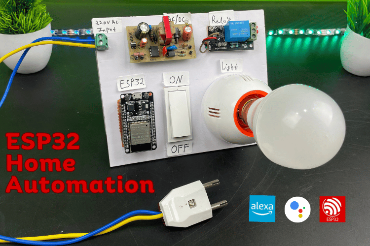
If you are new to smart home automation and are looking to build your first project to control your lights and fans with voice commands then this article is right for you. In this Internet of Things (IoT) project, I'll guide you through creating a Smart Home system that can be controlled using both Google Assistant and Alexa, using an ESP32 and Sinric Pro. If you are a home automation enthusiast and completely new here, then do check out our collection below for all the home automation projects that we have built here previously on CircuitDigest.
- Home Automation Projects
- ESP32 Projects
- Google Assistant Home Automation Projects
- Alexa Home Automation Projects
Now coming back to this project, we are using Sinric Pro so that can effectively control home appliances (like Light bulbs or fans) by seamlessly integrating voice commands through Google Assistant and Alexa, as well as using manual switches for control. But, once you understand the basic principle here, you can control every electrical appliance in the house using relays. As always we have given you the complete code and circuit diagram for this project and all the software used here in this project is free and readily available, that being said let's get started...
ESP32 Home Automation using Alexa and Google Assitant with Sinric Pro
Now, we need a platform that can bind our ESP32 with Google Assistant and Alexa, and for that, we have used something called Sinric Pro. It is very easy to use this platform and is free for limited use. For the purpose of this project, you can just use the free plan of Sinric Pro but if you want to control more devices from the same app you might wanna consider upgrading to a paid plan. In this ESP32 smart home project, we are going to control an AC bulb using Google Assistant, Alexa, and a manual switch all using Sinric Pro.
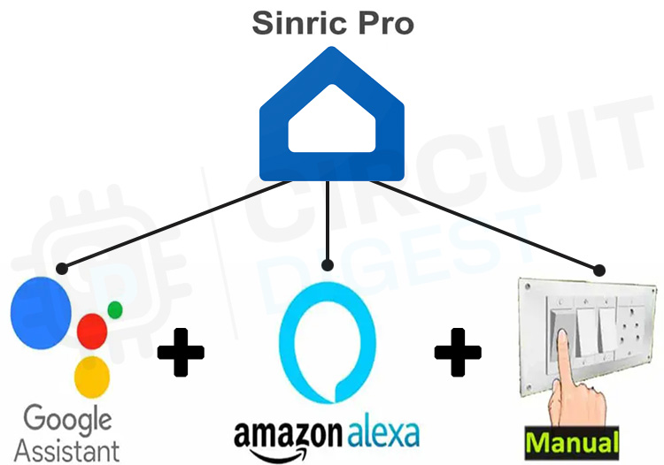
This means you have the flexibility to control your load using Google Home and the Amazon Alexa App, regardless of your location. And if there is no internet, you can still manage your appliances through the manual switches, without the need for additional devices like Google Nest or Amazon Echo Dot. This project brings the convenience of smart home automation to your fingertips.
Components Required for ESP32 Home Automation
- ESP32 Development Board
- 1-channel 5V SPDT Relay Module
- Manual Switch
- 5V - 2A AC/DC SMPS
- Light bulb
- Connecting wires or PCB (Printed Circuit Board)
ESP32 Home Automation Circuit Diagram
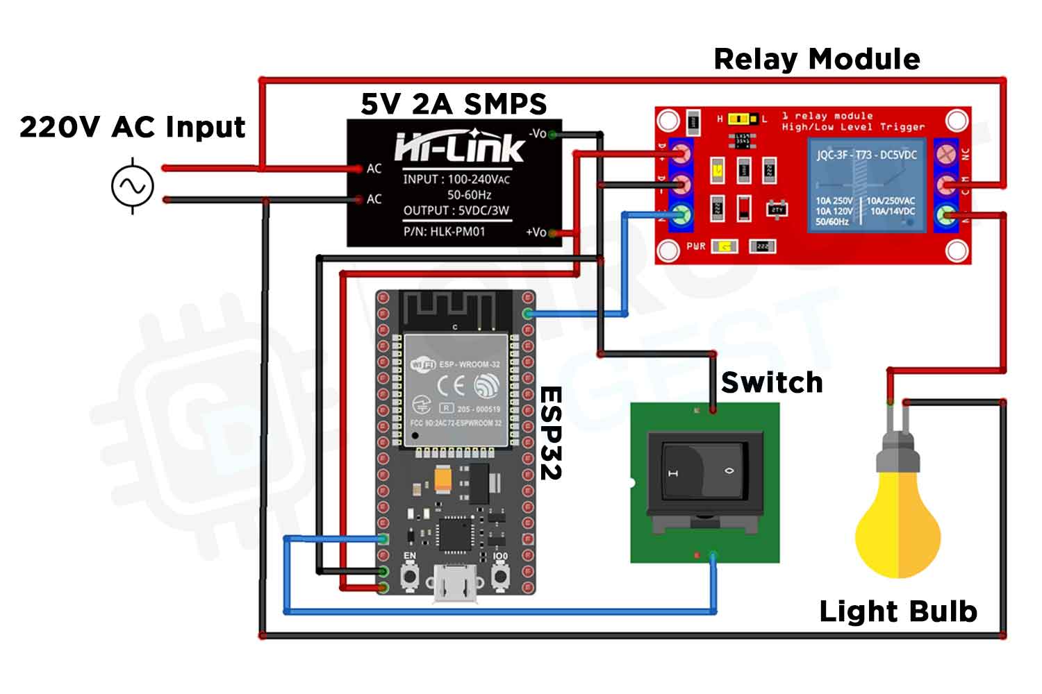
The circuit is very simple. I have used the D22 GPIO to control the relay module and the GPIO D12 connected with a manual switch to control the relay module manually. The complete circuit diagram for IoT-based home automation using esp32 is shown in the image below.
I have used a 5V 2Amp Switched-Mode Power Supply (SMPS) to convert AC to DC power, and this 5V supply is provided to both the ESP32 and the relay module. Based on the provided code, when the control pins of the relay module receive a LOW signal, the respective relay will turn on. Conversely, the relay will turn off when a HIGH signal is applied to the control pin. If you prefer to use pushbuttons, simply connect the pushbuttons between the GPIO pin and the GND pin instead of using switches.
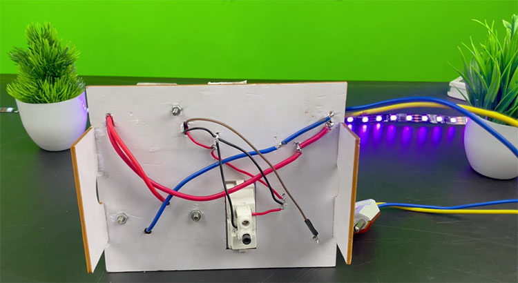
The above image shows the backside of my project board, you can see that I used a higher gauge wire for the AC and have maintained properly distance and insulation (was added later) between the phase and neutral line. Caution: Working with AC mains should need prior knowledge and experience. Please be careful and take adult supervision if needed.
In this tutorial video, I have covered the Assembly of the hardware with the required components and control relay with Google Assistant, Alexa and switch. The below image shows the final product after wiring, soldering, and assembly.
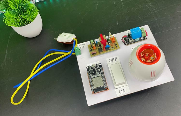
Setting up Sinric Pro for Smart Home Automation
In this home automation project, I used a Sinric Pro Free account which can control up to 3 loads for free. To get started, you'll need to add devices to your Sinric Pro account. I'll guide you through the process step by step, including creating a free account and adding your devices in Sinric Pro.
Another platform that is similar to Sinric Pro is Blynk, previously we have also built many projects using Blynk l like the IoT based smart Fan speed controller. But in recent times blynk has put limitations on free accounts, which is why we have used Sinric Pro. I have already written an article on the Difference Between Sinric Pro and Blynk you can also read that if interested.
With Sinric Pro, you can easily connect with Google Home and Amazon Alexa App with ESP8266, NodeMCU, or ESP32 microcontroller to control any appliance with Google Assistant and Alexa. So, you can easily make any IoT-based home automation project with Sinric Pro. As per their current plan you will get 3 devices for free. First visit sinric.pro/register
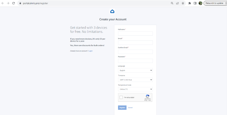
Then enter all the required details and click on Register. Then enter the email ID and password, and click on login.
Create a Room in Sinric Pro
Before adding the devices, first, you have to create room in the Sinric Pro.
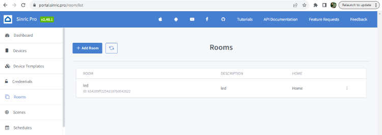
To create a room in the Sinric Pro account, follow the following steps. Goto Rooms in the left side menu. Click on the Add Room button. Enter the Room Name and Description. Click on Save.
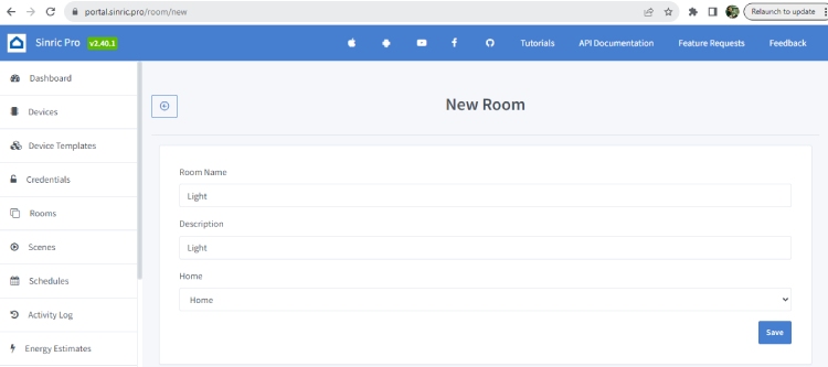
In this way, you can create multiple rooms as per your requirements.
How to Add Devices in Sinric Pro
If you use a Sinric Pro free account, then you can add 3 devices for free.

Please follow the following steps to add devices to the Sinric Pro account.

First, select the Devices from the left side menu, then click on the Add Device button.
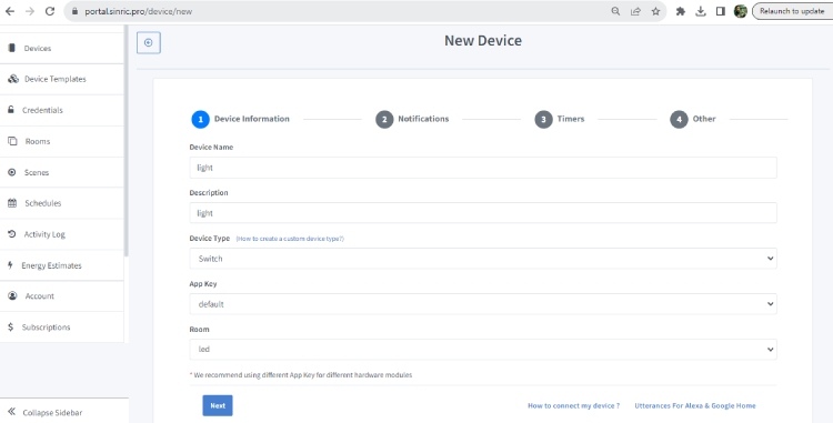
Enter the Device Name and Description. Then select the Device Type as per the requirement. Here I have selected the device type as Switch, as I will control the SPDT relay. Then select the Room for the device. After that click on Next.
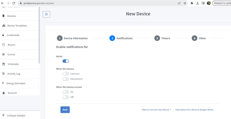
This field is optional. If you want any push notifications related to this device, then you can turn on the notifications. Click on Next.
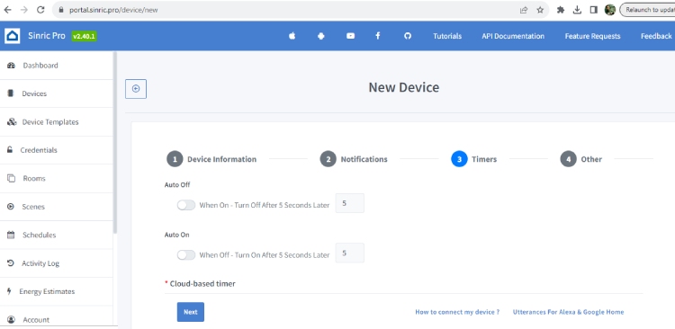
Again this field is optional. If you want to set any timer to Auto On or Auto Off the device, after the predefined time, then you the set here. Click on Next.
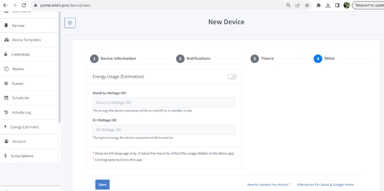
This is another optional field. You can define the wattage rating of the connected appliance to get the energy consumption estimation. Now Click on Save. Now, you successfully added one device on Sinric pro.
How to Get Sinric Pro API KEY, API SECRET & Device_ID
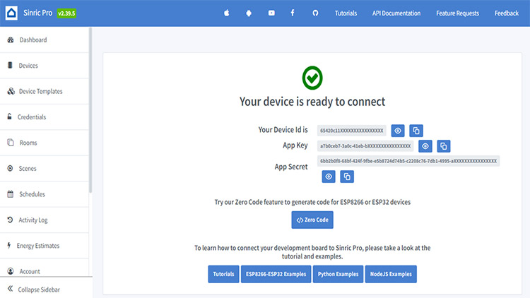
Before uploading any example sketch to ESP8266 or ESP32, you have to enter the Sinric API KEY and API SECRET. To get the API KEY and API SECRET, you have to go to Credentials from left side menu.

After that, Copy the APP KEY and APP SECRET and past into the code. Also enter the device id in the code. You will find the Device ID from Devices menu. This device Id is unique for each device. If you create 3 devices, then there will be 3 unique device IDs.

ESP32 Home Automation Code
Before you begin writing the code, there are several steps you need to follow to install essential libraries.
Update the Preferences –> Additional boards Manager with the below URL
URLs:https://dl.espressif.com/dl/package_esp32_index.json, http://arduino.esp8266.com/stable/package_esp8266com_index.json
Then install the ESP8266 board from the Board manager or manually download ESP8266 board then download the required libraries from the following links
- Sinric Pro by Boris Jaeger (Open library Manager search for Sinric Pro and click install for ESP8266 & ESP32)
- WebSockets by Markus Sattler (minimum Version 2.3.5)
- ArduinoJson by Benoit Blanchon (minimum Version 6.12.0)
Note: Download the latest versions of the libraries from the provided links. Afterward, install the libraries by going to Arduino IDE -> Sketch -> Include Library -> Add Zip Library.
You can also get the code files from CircuitDigest Github Page, the link for repo is given below
Code for ESP32 Home Automation using Google and Alexa
The ESP32 home automation code for Google Home and Alexa is straightforward. When we send the 'on' and 'off' commands using a smartphone, the signals are sent to the relay module, which in turn controls the light bulb turning it on and off. I have used the INPUT_PULLUP function in Arduino IDE instead of using the pull-up resistor with switch.
Make sure to replace "YourWiFiSSID", "YourWiFiPassword", "YourAppKey", and "YourAppSecret" with your actual credentials.
#define WIFI_SSID     "YOUR-WIFI-NAME"
#define WIFI_PASS     "YOUR-WIFI-PASSWORD"
#define APP_KEY       "YOUR-APP-KEY"
#define APP_SECRET    "YOUR-APP-SECRET"
Additionally, also replace "yourDeviceId" with your actual device ID. You will find the Device ID from the Devices menu in the Sinric Pro account. When you add a device in Sinric Pro, a unique ID is assigned to that device.
#define device_ID "SWITCH_ID_HERE"
ESP32 Home Automation Code
#include <Arduino.h>
#include <WiFi.h>
#include "SinricPro.h"
#include "SinricProSwitch.h"
In this block, the necessary libraries are included Arduino.h The core library for Arduino. WiFi.h The library for Wi-Fi connectivity. SinricPro.h The main SinricPro library for IoT integration. SinricProSwitch.h The library for creating a switch device using SinricPro.
#define WIFI_SSID         "YOUR-WIFI-NAME"

#define WIFI_PASS         "YOUR-WIFI-PASSWORD"

#define APP_KEY           "YOUR-APP-KEY"      // Should look like "de0bxxxx-1x3x-4x3x-ax2x-5dabxxxxxxxx"

#define APP_SECRET        "YOUR-APP-SECRET "   // Should look like "5f36xxxx-x3x7-4x3x-xexe-e86724a9xxxx-4c4axxxx-3x3x-x5xe-x9x3-333d65xxxxxx"
#define device_ID "SWITCH_ID_HERE"
In this block, you define your Wi-Fi network credentials (WiFi_SSID and WiFi_PASS) and the credentials for your SinricPro IoT application (APP_KEY and APP_SECRET). And also you define the device_ID, which represents the device ID associated with your switch in the SinricPro platform. Make sure to replace it with the actual device ID you've created.
#define RELAY_PIN    22 // D22
#define SWITCH_PIN   12 // D12
#define wifiLed   2   //D2
This block defines the GPIO pins used for the relay, switch, and the Wi-Fi LED indicator. RELAY_PIN is the pin connected to the relay, SWITCH_PIN is the pin connected to the manual switch, and wifiLed is the pin used to indicate Wi-Fi connection status.
bool lastSwitchState = true;
unsigned long lastSwitchChange = 0;
bool relayState = false;
Here, you declare global variables that will be used throughout the sketch lastSwitchState keeps track of the previous state of the manual switch. lastSwitchChange records the time of the last switch state change. relayState represents the current state of the relay.
bool onPowerState(const String& deviceId, bool &state) {
  relayState = state;
  digitalWrite(RELAY_PIN, !relayState);
  return true;
}
This function is a callback that is called when the power state of the switch changes, either manually or through the SinricPro service. It toggles the relay's state (relayState) and returns true.
void handleSwitch() {
  unsigned long currentMillis = millis();
  bool switchState = digitalRead(SWITCH_PIN);
  if (switchState != lastSwitchState) {
    if (currentMillis - lastSwitchChange > DEBOUNCE_TIME) {
      if (switchState) {
        relayState = !relayState;  // Toggle the relay state
        digitalWrite(RELAY_PIN, relayState);
        SinricProSwitch &mySwitch = SinricPro[device_ID];
        mySwitch.sendPowerStateEvent(relayState);
      }
      lastSwitchChange = currentMillis;
    }
    lastSwitchState = switchState;
  }
}
The handleSwitch function is responsible for monitoring the manual switch for state changes. It uses the global variables to keep track of the switch state changes and debounce the switch. When a change is detected, it toggles the relay state and sends a power state event to SinricPro to keep it in sync.
void setupWiFi()
{
  Serial.printf("\r\n[Wifi]: Connecting");
  WiFi.begin(WIFI_SSID, WIFI_PASS);
  while (WiFi.status() != WL_CONNECTED)
  {
    Serial.printf(".");
    delay(250);
  }
  digitalWrite(wifiLed, HIGH);
  Serial.printf("connected!\r\n[WiFi]: IP-Address is %s\r\n", WiFi.localIP().toString().c_str());
}
The setupWiFi function is responsible for connecting to your Wi-Fi network. It prints a connection progress message. It waits until a successful connection is established and then prints the device's IP address.
void setupSinricPro() {
  SinricProSwitch& mySwitch = SinricPro[device_ID];
  mySwitch.onPowerState(onPowerState);
  SinricPro.begin(APP_KEY, APP_SECRET);
  SinricPro.restoreDeviceStates(true);
}
This function is responsible for setting up the Sinric Pro service for your IoT project. Here's what it does. SinricProSwitch&mySwitch = SinricPro[device_ID] This line creates an instance of the SinricProSwitch class with the provided device_ID. This class represents the switch you want to control using Sinric Pro. mySwitch.onPowerState(onPowerState) Here, you register the onPowerState function as the callback for handling power state changes. When a command is sent to turn the switch on or off, this function will be called. SinricPro.begin(APP_KEY, APP_SECRET) Initializes the Sinric Pro service with your APP_KEY and APP_SECRET, which are unique identifiers for your Sinric Pro account. SinricPro.restoreDeviceStates(true) This line tells Sinric Pro to restore the device's state upon connection.
void setupRelay() {
  pinMode(RELAY_PIN, OUTPUT);
digitalWrite(RELAY_PIN,HIGH); // Initialize relay in the OFF state
This function is for setting up the relay pin pinMode(RELAY_PIN, OUTPUT) It configures the RELAY_PIN as an output pin, which is typically connected to a relay module that controls your light bulb. digitalWrite(RELAY_PIN, HIGH) It initializes the relay in the OFF state by setting the pin to HIGH.
void setupSwitch() {
  pinMode(SWITCH_PIN, INPUT_PULLUP);
}
This function is for setting up the manual switch pin pinMode(SWITCH_PIN, INPUT_PULLUP) It configures the SWITCH_PIN as an input pin with a pull-up resistor. This setup is common for manual switches.
void setup() {
  Serial.begin(BAUD_RATE);
  pinMode(wifiLed, OUTPUT);
  digitalWrite(wifiLed, LOW);
  setupRelay();
  setupSwitch();
  setupWiFi();
  setupSinricPro();
}
The setup() function is where the initial setup of your IoT project takes place. Here's what happens: It initializes the serial communication for debugging Serial.begin(BAUD_RATE) It sets up the LED wifiLed to indicate the status of the Wi-Fi connection. Calls setupRelay() to configure the relay pin. Calls setupSwitch() to configure the manual switch pin. Calls setupWiFi() to connect to the Wi-Fi network. Calls setupSinricPro() to initialize the Sinric Pro service.
void loop() {
  SinricPro.handle();
  handleSwitch();
}
The loop() function is the main execution loop of your IoT project. It does the Calls SinricPro.handle() to handle incoming messages from Sinric Pro. Calls handleSwitch() to monitor the state of the manual switch and update the relay accordingly. This function is not explicitly defined in the code snippet you provided, but it is likely defined elsewhere in your code to manage manual switch input.
This code sets up your ESP32 home automation project to work with Sinric Pro, handles relay control, and monitors the manual switch for changes in state. It allows you to control a connected device using both Sinric Pro and the manual switch.
ESP32 Alexa Home Automation
First, download and install the Amazon Alexa App from Google Play Store or App Store.
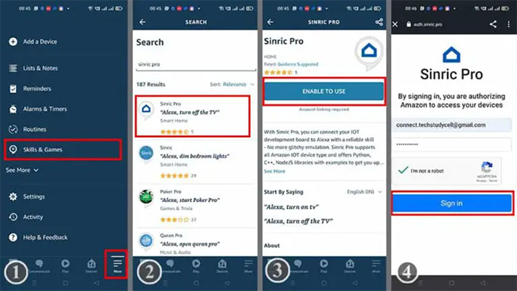
Before connecting the Alexa, it is necessary to include devices in the Sinric Pro platform. In the Alexa App, Tap to More, then select Skills & Games. Search for Sinric Pro, and choose Sinric Pro from the results. Enable usage by tapping ENABLE TO USE. Input the email address and password associated with the Sinric account, and then proceed by tapping Sign in.
After connecting the Sinric Pro account, follow the following steps to add devices.
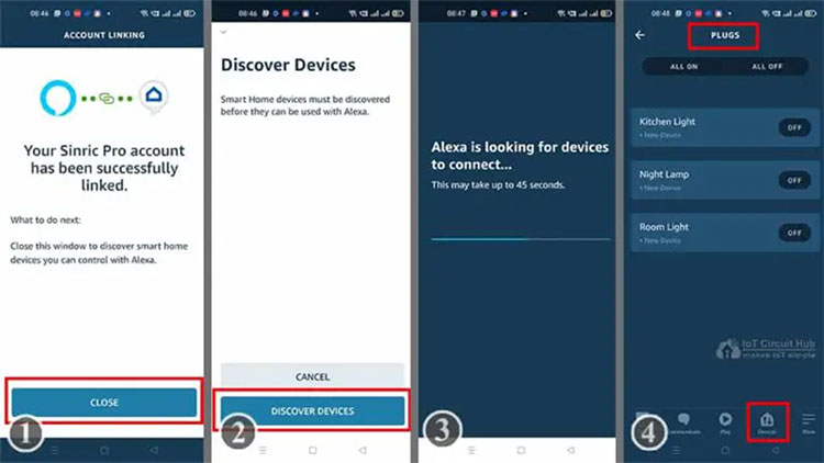
Tap on CLOSE. Tap on DISCOVER DEVICES. Now, Alexa will look for new devices. This may take some time. After that, go to Devices, then select Plug. You will find all the connected devices.
Now, if the ESP32 is connected to the Wi-Fi, then you can control the appliances from the Alexa App. You can also say “Alexa, Turn ON light” to control the appliances with voice commands.
ESP32 Google Home Integration
First, download and install the Google Home App from Google Play Store or App Store.
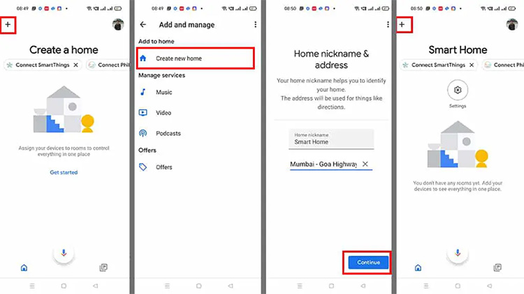
In the Google Home App, follow the following steps to create a Home. Click on the “+” icon (upper left corner). Tap on Create new home. Enter the Home nickname and address. Then tap on Continue. The Home is created. Now again tap on the “+” icon to add devices.
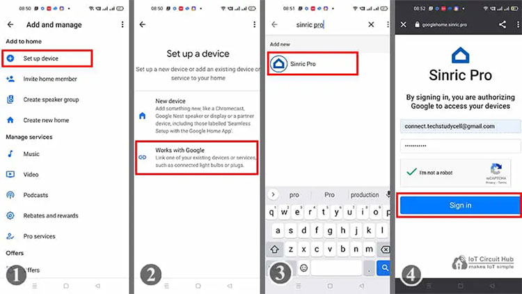
After setting up your Home in the Google Home app, you can establish a connection between Sinric Pro and the Google Home app. Before connecting with Google Home, ensure that you have added devices to Sinric Pro. Follow the steps below to add devices.
Click on the “+” icon, then choose Set up device. Select Works with Google and search for Sinric Pro, then click on Sinric Pro. Input the email ID and password associated with your Sinric account, then click Sign in. Afterward, return to the home screen of the Google Home app. You will now be able to view all the devices in your Google Home app.
After linking Sinric Pro, go to the homepage of the Google Home app. You'll find the connected devices from Sinric Pro. If the ESP32 is connected to Wi-Fi, you can control the appliances through the Google Home app. You can also command Google Assistant by saying, “Hey Google, Turn ON light” to control the appliances.
ESP32 Smart Home Automation with Google Assistant and Alexa
After doing all these steps, now you control the light bulb with Manual Switch, Google Assistant and Alexa.
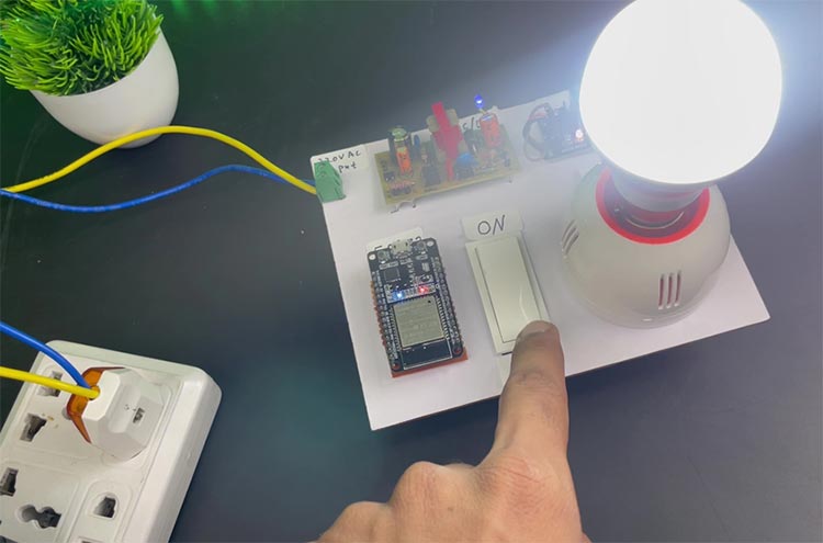
To control the light bulb with a switch or push button just turn on and off the button. And if the ESP32 is connected with the Wi-Fi, then you can monitor the real-time status in Google Home and Alexa App.
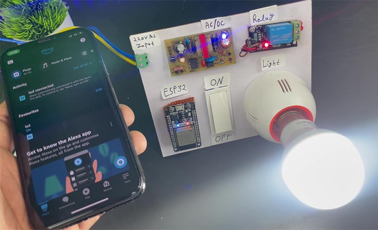
If the ESP32 is connected with WiFi, then you can ask Alexa to turn on the light [“Alexa, Turn ON Light“]. Thus, you can control the light with voice commands using Amazon Alexa App, and also monitor the current status of the switches from anywhere in the world from the Alexa App.
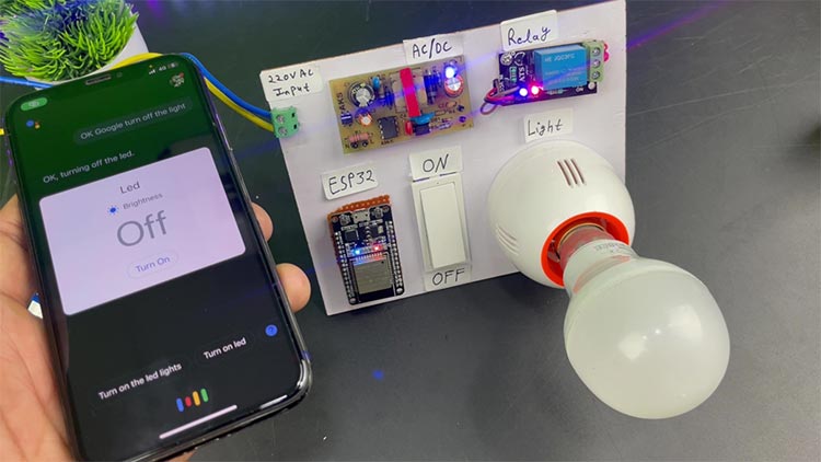
You can also ask Google Assistant to turn on the light [“Hey Google, Turn ON the Light“]. Thus, you can control the light with voice commands using Google Assistant, and also monitor the current status of the switches from anywhere in the world from the Google Home App.
With this we have come to an conclusion for this project, for more DIY smart home automation projects check out our Arduino Voice Controlled Home Automation, Temperature based Smart Fan and Bluetooth controlled Smart Home. Hope you enjoyed reading this tutorial, if you have any questions please feel free to write in our forums and we will try our best in helping you out.
//ESP32 Home Automation Code
//by CircuitDigest
#include <Arduino.h>
#include <WiFi.h>
#include "SinricPro.h"
#include "SinricProSwitch.h"
#define WIFI_SSID "YOUR-WIFI-NAME"
#define WIFI_PASS "YOUR-WIFI-PASSWORD"
#define APP_KEY "YOUR-APP-KEY" // Should look like "de0bxxxx-1x3x-4x3x-ax2x-5dabxxxxxxxx"
#define APP_SECRET "YOUR-APP-SECRET" // Should look like "5f36xxxx-x3x7-4x3x-xexe-e86724a9xxxx-4c4axxxx-3x3x-x5xe-x9x3-333d65xxxxxx"
#define device_ID "SWITCH_ID_HERE"
#define RELAY_PIN 22 // D22
#define SWITCH_PIN 12 // D12
#define wifiLed 2 //D2
#define BAUD_RATE 9600
#define DEBOUNCE_TIME 250
bool lastSwitchState = true;
unsigned long lastSwitchChange = 0;
bool relayState = false;
bool onPowerState(const String& deviceId, bool &state) {
relayState = state;
digitalWrite(RELAY_PIN, !relayState);
return true;
}
void handleSwitch() {
unsigned long currentMillis = millis();
bool switchState = digitalRead(SWITCH_PIN);
if (switchState != lastSwitchState) {
if (currentMillis - lastSwitchChange > DEBOUNCE_TIME) {
if (switchState) {
relayState = !relayState; // Toggle the relay state
digitalWrite(RELAY_PIN, relayState);
SinricProSwitch &mySwitch = SinricPro[device_ID];
mySwitch.sendPowerStateEvent(relayState);
}
lastSwitchChange = currentMillis;
}
lastSwitchState = switchState;
}
}
void setupWiFi()
{
Serial.printf("\r\n[Wifi]: Connecting");
WiFi.begin(WIFI_SSID, WIFI_PASS);
while (WiFi.status() != WL_CONNECTED)
{
Serial.printf(".");
delay(250);
}
digitalWrite(wifiLed, HIGH);
Serial.printf("connected!\r\n[WiFi]: IP-Address is %s\r\n", WiFi.localIP().toString().c_str());
}
void setupSinricPro() {
SinricProSwitch& mySwitch = SinricPro[device_ID];
mySwitch.onPowerState(onPowerState);
SinricPro.begin(APP_KEY, APP_SECRET);
SinricPro.restoreDeviceStates(true);
}
void setupRelay() {
pinMode(RELAY_PIN, OUTPUT);
digitalWrite(RELAY_PIN,HIGH); // Initialize relay in the OFF state
}
void setupSwitch() {
pinMode(SWITCH_PIN, INPUT_PULLUP);
}
void setup() {
Serial.begin(BAUD_RATE);
pinMode(wifiLed, OUTPUT);
digitalWrite(wifiLed, LOW);
setupRelay();
setupSwitch();
setupWiFi();
setupSinricPro();
}
void loop() {
SinricPro.handle();
handleSwitch();
}

