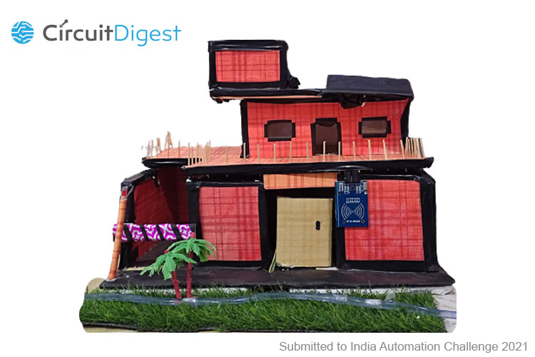
I have built a model of a Modern Smart Home. These features demonstrate what a Smart Home would be like! A smart home refers to a convenient home setup where all the appliances and devices can be automatically controlled remotely. Devices in such a smart home are interconnected, allowing the user to control functions such as security access to the home, temperature, humidity, etc. It is one of the applications of Smart technologies within our home automation, in creating a comfortable home and an effective lifestyle. It improves automation control and monitoring of household devices and Connects via standard means of communication for its operation. In this Era of Technology, the next big thing after Smart Phones will be a Smart Home. I made this project because I wanted to create something which should be Futuristic and Future Proof. I made this project to show how we can implement the latest technologies in our homes to make our lives easier. To bring this next level experience of interacting with your home and appliances, to the people! I am using two Arduinos in my Project. The First Arduino which is the Slave Arduino is connected to all the sensors and when a Sensor gets triggered the Slave Arduino sends data to Master Arduino, which is connected to the HC-05 Bluetooth Module, Relay, and all the Servo Motors. The master Arduino then Computes the data and performs the Respective Operation. The App which I have made is connected to the master Arduino through Bluetooth. The App converts your speech to text and sends data to Master Arduino, which then performs the Respective Operation. The app constantly runs in the background and receives data from Master Arduino, computes the data, and gives you a Notification, a Voice Message, and a Text Message.
Previously, we have built many home automation projects, you can check them out
- Smart Phone Controlled Home Automation Using Arduino
- IoT based Voice Controlled Home Automation using ESP8266 and Android App
- Modular Home Automation System with Arduino
- RF Controlled Home Appliances
- GUI Based Home Automation System using Arduino and MATLAB
- Home Automation using Node-RED and Home Assistant on Raspberry Pi
What's New
- It is inexpensive and easy to implement.
- I have coded a timer in the App which can be used to automate time-dependent operations.
- The App constantly works in the background and constantly notifies the user.
The Unique Selling Proposition(USP) of my Smart Home is-
- User Interface easy to control.
- Just one click to operate all the features.
- Everything is Voice enabled.
- A non-specialist can also use these features without any hassle.
- Cheaper than other Smart Homes as there is no longer an elaborate system to control the Smart Home.
The Potential Applications of my Smart Home are-
- Individual Houses
- Offices
- Big societies
- Cars
- Schools
- Industries
- Shops
Components for Futuristic Smart Home

Project Used Hardware
- Arduino UNO,
- L298N Motor Driver,
- Servo Motors,
- Relay,
- Sensors(Flame Sensor, IR Sensor, Rain Sensor)
Project Used Software
- Arduino IDE,
- MIT App Inventor
Project Hardware Software Selection
Arduino Uno(Brain of the Smart Home) - The Arduino Uno is one of the most common Arduino boards available, and it has some user-friendly features, including large 2.54mm pitched sockets for connecting to external devices, an onboard LED, inbuilt power handling (such as an external DC power jack), and a large USB B connector for connecting to a PC.
L298N H-Bridge Motor Driver - L298N is an integrated circuit multi-watt 15 package and capable of giving high voltage. It is a high current dual full-bridge driver that is designed to accept standard TTL logic levels. It can drive inductive loads e.g relays, solenoids, motors (DC and stepping motor), etc.
Servo Motor - Controlled Intelligent Motion
Sensors - I have used sensors that are compatible with Arduino Uno and user-friendly.
Arduino IDE - Arduino works perfectly with all Arduino Boards, it's Inexpensive and Open Source. MIT App Inventor - Everything is done through a select and drop manner, Easy to test your app.
Circuit Diagram
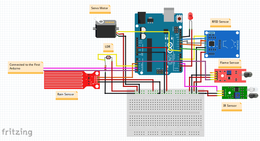
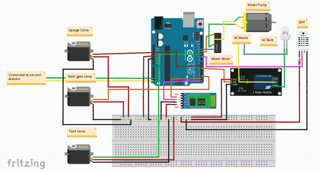
I am using two Arduinos in my Project. The First Arduino which is the Slave Arduino is connected to all the sensors and when a Sensor gets triggered the Slave Arduino sends data to Master Arduino, which is connected to the HC-05 Bluetooth Module, Relay, and all the Servo Motors. The master Arduino then Computes the data and performs the Respective Operation. The App which I have made is connected to the master arduino through bluetooth. I am using the l2C Protocol for Communication between the two Arduinos.
For Arduino 1(Master Arduino):
- The Temperature and Humidity Sensor is connected to pin 9.
- The Main Gate Servo, Tank Servo and the Garage Servo are Connected to the pins 2,10 and 6 Respectively.
- The Relay Module is connected to pin 4.
For Arduino 2(Slave Arduino):

- The SDA, SCK, MOSI, MISO and RST Pins are Connected to the Pins 5,13,11,12 and 5 Respectively.
- The Flame Sensor, IR Sensor, LDR and Rain Sensor are Connected to the pins A1,3,A3 and A2.
- The Servo Motor is Connected to pin 8.
#include <DHT.h>
#include <Wire.h>
//including servo library
#include<Servo.h>
int x;
#define DHTPIN 9
#define DHTTYPE DHT11
DHT dht(DHTPIN, DHTTYPE);
int pos = 0;
//creating servo object
Servo myservo;
Servo tank;
//automatic home lights
int led_ac = 4;
//automatic garage
Servo servo_garage;
void setup()
{
  pinMode(led_ac , OUTPUT);
  pinMode(11 , OUTPUT);
  pinMode(12 , OUTPUT);
  myservo.attach(2);
  tank.attach(10);
  servo_garage.attach(6);
  dht.begin();
  Wire.begin(8);
  Wire.onReceive(receive);
  myservo.write(0);
  servo_garage.write(30);
  digitalWrite(led_ac, HIGH);
  Serial.begin(9600);
}

void loop()
{
  if (Serial.available())
  {
    int a = Serial.read();
    Serial.println(a);
    //automatci home lights
    if (a == 6)
    {
      digitalWrite(led_ac, HIGH);
    }
    if (a == 7)
    {
      digitalWrite(led_ac, LOW);
    }
    //automatic garage
    if (a == 8)
    {
      servo_garage.write(140);
    }
    if (a == 9)
    {
      servo_garage.write(30);
    }
    //smart home gate
    if (a == 10)
    {
      for (pos = 0; pos <= 90; pos += 1)
      {
        myservo.write(pos);
        delay(15);
      }
      delay(5000);
      for (pos = 90; pos >= 0; pos -= 1)
      {
        myservo.write(pos);
        delay(15);
      }
    }
    //temperature and humidity measurment
    if (a == 11)
    {
      float h = dht.readHumidity();
      Serial.print(h);
      delay(3000);
    }
    if (a == 12)
    {
      float t = dht.readTemperature();
      Serial.print(t);
      Serial.println("°C ");
      delay(3000);
    }
    if (a == 19)
    {
      digitalWrite(11, HIGH);
      digitalWrite(12, LOW);
    }
    if (a == 20)
    {
      digitalWrite(11, LOW);
      digitalWrite(12, LOW);
    }
  }
  else
  {
    if (x == 13)
    {
      for (pos = 0; pos <= 90; pos += 1)
      {
        myservo.write(pos);
        delay(15);
      }
      delay(5000);
      for (pos = 90; pos >= 0; pos -= 1)
      {
        myservo.write(pos);
        delay(15);
      }
    }
    if (x == 2)
    {
      tank.write(180);
    }
    if (x == 16)
    {
      tank.write(90);
    }
  }
}
void receive(int howMany)
{
  x = Wire.read();
  Serial.println(x);
}

............................................................................................................................................................................

#include<Servo.h>
#include <Wire.h>
#include <SPI.h>
#include <MFRC522.h>
#define SS_PIN 5
#define RST_PIN 9
MFRC522 mfrc522(SS_PIN, RST_PIN);
//Smart Street Lights
int ldr = A3;
int led_street = 2;
//fire detector
int fire = A1;
//Rain detector
int rain = A2;
Servo servo_rain;
//SMART GATE
int sensor_gate = 3;
void setup()
{
  pinMode(fire, INPUT);
  pinMode(ldr, INPUT);
  pinMode(rain, INPUT);
  pinMode(sensor_gate, INPUT);
  servo_rain.attach(8);
  Serial.begin(9600);
  Wire.begin();
  servo_rain.write(90);
  SPI.begin();      // Initiate  SPI bus
  mfrc522.PCD_Init();   // Initiate MFRC522
  Serial.println("Put your card to the reader...");
}
void loop()
{
  //smart gate
  int sensor_gate_value = digitalRead(sensor_gate);
  if (sensor_gate_value == LOW)
  {
    Wire.beginTransmission(8);
    Wire.write(3);
    Wire.endTransmission();
    delay(2000);
    Wire.beginTransmission(8);
    Wire.write(16);
    Wire.endTransmission();
  }
  //fire detector
  int fire_value = digitalRead(fire);
  if (fire_value == LOW)
  {
    Wire.beginTransmission(8);
    Wire.write(1);
    Wire.endTransmission();
    delay(4000);
    Wire.beginTransmission(8);
    Wire.write(16);
    Wire.endTransmission();
  }
  //Rain detector
  int rain_value = digitalRead(rain);
  if (rain_value == LOW)
  {
    servo_rain.write(0);
    Wire.beginTransmission(8);
    Wire.write(2);
    Wire.endTransmission();
    delay(4000);
    Wire.beginTransmission(8);
    Wire.write(16);
    Wire.endTransmission();
  }
  else
  {
    servo_rain.write(90);
  }
  //Smart Street Lights
  int ldr_value = analogRead(ldr);
  if (ldr_value <= 48)
    digitalWrite(led_street, HIGH);
  else
    digitalWrite(led_street, LOW);

  if ( ! mfrc522.PICC_IsNewCardPresent())
  {
    return;
  }
  // Select one of the cards
  if ( ! mfrc522.PICC_ReadCardSerial())
  {
    return;
  }
  //Show UID on serial monitor
  Serial.print("UID tag :");
  String content = "";
  byte letter;
  for (byte i = 0; i < mfrc522.uid.size; i++)
  {
    Serial.print(mfrc522.uid.uidByte[i] < 0x10 ? " 0" : " ");
    Serial.print(mfrc522.uid.uidByte[i], HEX);
    content.concat(String(mfrc522.uid.uidByte[i] < 0x10 ? " 0" : " "));
    content.concat(String(mfrc522.uid.uidByte[i], HEX));
  }
  Serial.println();
  Serial.print("Message : ");
  content.toUpperCase();
  if (content.substring(1) == "89 A9 BB 98") //change here the UID of the card/cards that you want to give access
  {
    Serial.println("Authorized access");
    Serial.println();
    Wire.beginTransmission(8);
    Wire.write(13);
    Wire.endTransmission();
    delay(5000);
    Wire.beginTransmission(8);
    Wire.write(15);
    Wire.endTransmission();
  }
  else
  {
    Serial.println("Access denied");
    Wire.beginTransmission(8);
    Wire.write(14);
    Wire.endTransmission();
    delay(4000);
  }
}


how can i get the app please ??