In 2019, Arduino Platform introduced Arduino Cloud IoT which is an end-to-end solution to help IoT enthusiasts and professionals in making connected projects easily. Arduino IoT Cloud provides a full-stack approach that is ready-to-use, by combining hardware, firmware, cloud services, and knowledge support needed to deliver an end-to-end IoT solution. This IoT Cloud Platform enables users to collect, graph, and analyze their sensor data, trigger events, and fully control their devices. This way, users can automate their homes or businesses with ease, all in a single place.
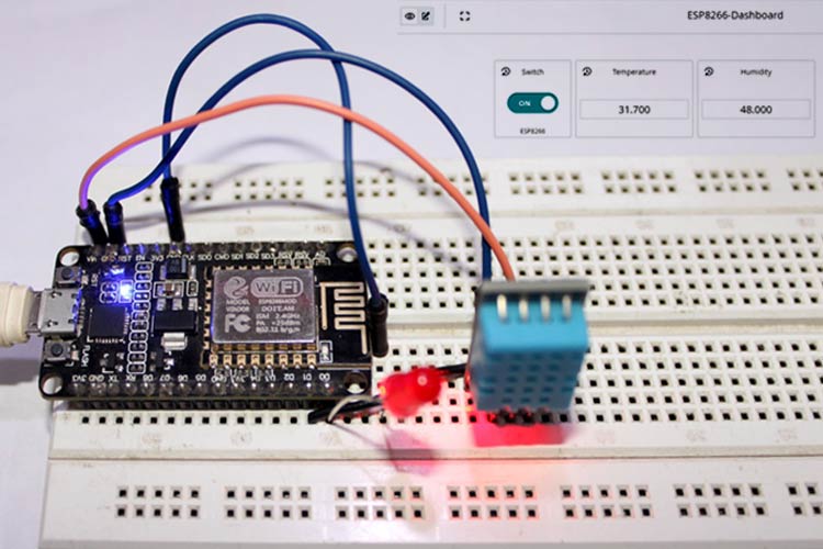
So, in this tutorial, we are going to set up the NodeMCU-ESP8266 with the Arduino Cloud IoT. To test it out, we will send DHT11 sensor data from the board to the cloud, and set up a switch that can control the LED connected to NodeMCU.
Arduino Cloud IoT – Key Features and Limitations
Arduino Cloud IoT platform enables users to write code, compile and upload directly from their browser, connect their IoT devices, and build real-time dashboards. It automatically generates a sketch when setting up a new thing according to the variables defined. All the features of Arduino Cloud IoT are listed below:
Automatically generated code: The Arduino Cloud IoT automatically generates a sketch according to the variables that the user defines while setting up a Thing, thus it removes barriers for users who are not familiar with coding and empowering makers of all ages and experiences.
Plug & Play onboarding: Using the Arduino cloud IoT platform, you can write code, compile and upload directly from your browser, connect your IoT devices, and build real-time dashboards. So, you don’t need to move to Arduino IDE for programming the hardware.
‘On-the-go’ mobile dashboard: This enables users to access, check data, and control remote sensor monitoring from anywhere using accessible widgets.
Integration with Other Platforms: Arduino Cloud IoT can be integrated with Amazon Alexa, Google Sheets, IFTTT, and ZAPIER, which enables users to program and manage devices using voice, spreadsheets, databases, and automate alerts using webhooks. The platform also enables developers to create custom apps using the Arduino IoT API, with custom endpoint webhooks to be added for further flexibility.
With all these features, Arduino Cloud IoT has some limitations too. One of them is that it only works with certain Arduino and ESP boards. All the supported boards are listed below:
Arduino Boards
- Arduino NANO 33 IoT
- Arduino MKR Wi-Fi 1010
- Arduino MKR WAN 1310
- Arduino MKR WAN 1300
- Arduino MKR NB 1500
- Arduino MKR GSM 1400
- Arduino MKR1000
- Arduino Portenta H7 (M7 core)
- Arduino Nano RP2040 Connect
ESP and Other Boards
- ESP8266
- ESP32
- Pelion
- Generic LoRa
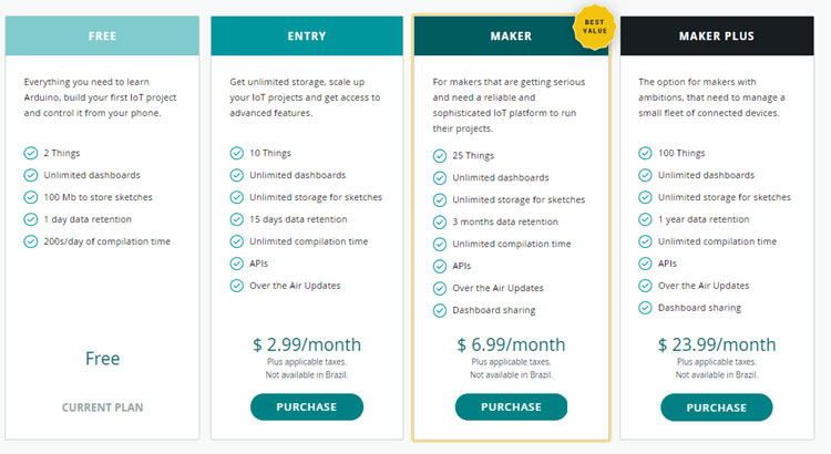
And using the Arduino Cloud IoT free plan, users can add only two devices and it provides a limited compilation time of 200 s/day. So, if you want to connect more than two devices you have to buy a premium plan. Currently, Arduino cloud IoT offers four different plans with different features and prices. All the plans are summarized in the below image:
Components Required for Connecting ESP8266 to Arduino Cloud IoT
- NodeMCU ESP8266
- DHT11 Sensor
- LED (5mm)
Circuit Diagram for Connecting ESP8266 to Arduino Cloud IoT
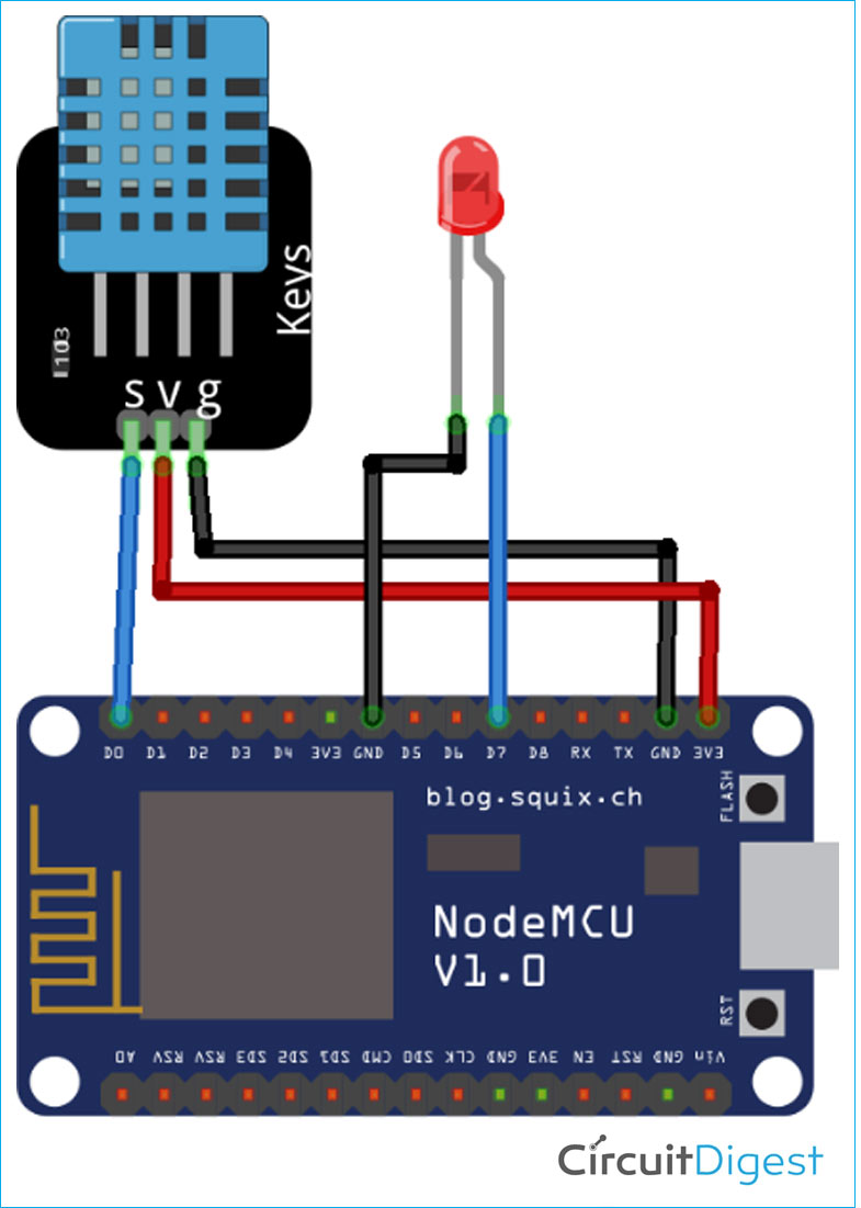
Circuit Diagram for sending DHT11 sensor data to the Arduino IoT cloud is given below.
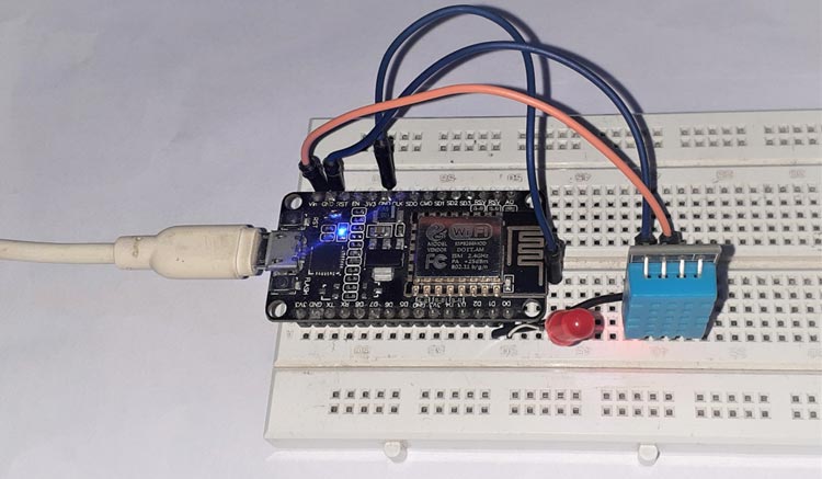
Connections are pretty simple. DHT11 sensor is powered through 5V and GND pin of NodeMCU. The data pin of DHT11 is connected to D0 of NodeMCU and the positive lead of LED is connected to the D7 pin of NodeMCU.
Setting Up the Arduino Cloud IoT
Now that we have connected the required hardware, let’s set up the Arduino Cloud IoT for ESP8266. For that sign in to your Arduino account. If you don’t have an account already, head over to the Arduino Cloud IoT and create one.
Step1: Once the account setup is complete, we will add a new device, i.e. NodeMCU to Arduino Cloud IoT. In the cloud, go to the "Devices" tab. Then, click on the "Add device" button.

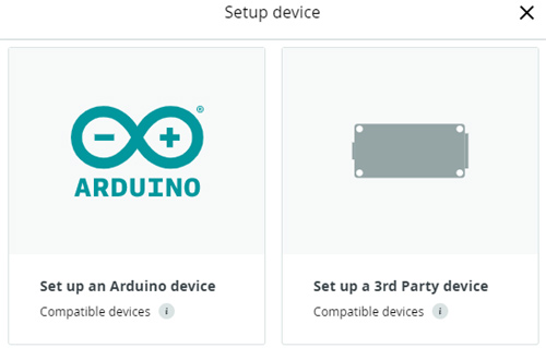
Then, click on "Set up a 3rd party device".
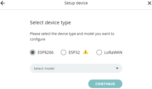
In the next step, we need to select the development board that we are using. First, select ESP8266 in device type, and then choose the NodeMCU1.0 from the drop-down menu.
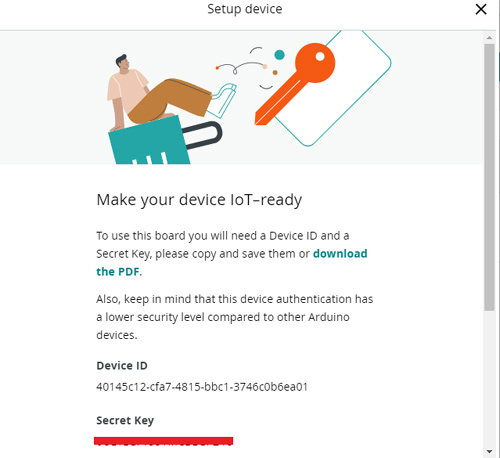
Next, rename the device as per your project and click next. A window will pop up with the Device ID and Secret Key for that device. You can either note it down or click on the “download the PDF” to save the details on your local system. Please note that the secret key cannot be recovered.
Then click on CONTINUE to add the device.
Step2: After adding the device, the next step is to create a Thing. So go to the "Things" tab and click on ‘Create Thing’.

Now, on the Things tab, we have three options to configure i.e., Variables, Device, and Network. First, we will link our device with our Thing. This can be done by clicking on the Link icon button in the "Device" section. This will open a window, where your recently created Device should be available to select.
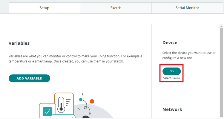
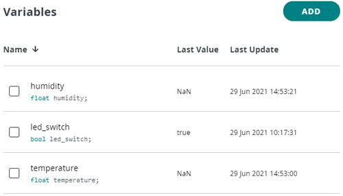
Once the device is linked, we need to add some variables that will be used in the code. Click on the "Add variable" button. This will open a window where you need to fill in variable information. Here, we will create three variables out of which, one will be used for LED, and two will be used for storing temperature and humidity values.
Let's create the led_switch first. The data type is int, permission is read-only and the update policy is on change. Once done, click on the "Add variable" button.
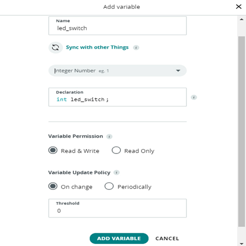
Similarly, add ‘temperature’ and ‘humidity’ variables. The data type for these variables is float, the permission is read & write, and the update policy is on change.
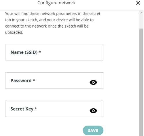
Now, in the next step, we need to enter the Wi-Fi credentials and the secret key is generated during the device configuration. For that click on the ‘Configure’ button in the "Network Section". Enter the credentials and then click on ‘Save.’
Step3: Now that we have added the device and the variables, we can move on to the next step, which is creating a dashboard. For that, go to the ‘Dashboard’ tab and click on the ‘Build Dashboard’ button.

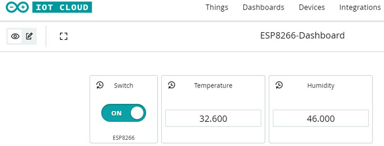
To add the widgets on the dashboard, click on the pencil icon at the top left corner, click on the ‘Add’ button and then go to "Things" and select the Thing. Then select all the variables and click on "Add widgets".
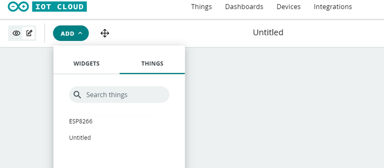
The final desktop screen will look like this:

Programming NodeMCU for Sending Data to Cloud
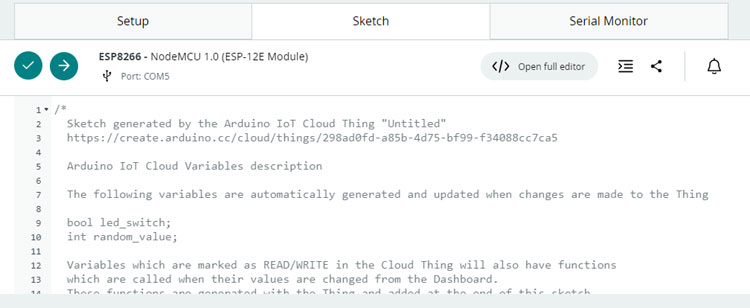
We are now done with setting up the Arduino Cloud IoT, the next step is to program the NodeMCU to read the data from DHT11 and send it to Arduino Cloud. To do so, we need to go to the "Sketch" tab.
When you add any variable in Things, the Sketch on the cloud is automatically updated according to the variables. So, most of the code is already written and we only need to add some lines for the DHT11 sensor. The complete code is given below.
When the code is ready, select the Board and Port and hit the upload button in the top left corner.
With this done now, you can control LED and monitor the DHT11 sensor data using the Arduino Cloud IoT platform.
Hope you enjoyed building the project and learned something new, if you have any questions, leave them in the comment section below or use our forum.
#include "thingProperties.h"
#include "DHT.h"
#define DHTTYPE DHT11   // DHT 11
#define dht_dpin 1
DHT dht(dht_dpin, DHTTYPE);
int LED = D0;
void setup() {
  // Initialize serial and wait for port to open:
  Serial.begin(9600);
  pinMode(LED, OUTPUT);
  // This delay gives the chance to wait for a Serial Monitor without blocking if none is found
  delay(1500);
  // Defined in thingProperties.h
  initProperties();
  // Connect to Arduino IoT Cloud
  ArduinoCloud.begin(ArduinoIoTPreferredConnection);
  /*
     The following function allows you to obtain more information
     related to the state of network and IoT Cloud connection and errors
     the higher number the more granular information you’ll get.
     The default is 0 (only errors).
     Maximum is 4
 */
  setDebugMessageLevel(2);
  ArduinoCloud.printDebugInfo();
}
void loop() {
  ArduinoCloud.update();
  // Your code here
  temperature = dht.readTemperature();
  humidity = dht.readHumidity();
}
void onLedSwitchChange() {
  // Do something
  if(led_switch){
    digitalWrite(LED, LOW);
  }
  else{
    digitalWrite(LED, HIGH);
  }
}
void onTemperatureChange() {
}
void onHumidityChange() {
}
