As a human, if you were asked to select your favourite food or favourite car, how would you compare your choices and conclude an answer? Of course, the answer for the above varies from person to person depending upon their personal preferences and the result will depend on individual choices. It’s a cardinal aspect of our life but the main picture here is that we humans have a selection process to compare between our options and reach a conclusion.
Now, what if we want to do the same thing with electronics? Is there any device/component that paves the way to select the data depending on our choice? Yes, there is a solution to this question. In the digital electronic world, a combinational circuit named “Multiplexer" is a device that is commonly used for the selection process. Let us delve deep into what is a Multiplexer, its specifications, and how can we design one using VHDL on Modelsim. If you are new here, do check out our previous VHDL tutorials using ModelSim.
What is a Multiplexer?
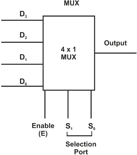
Just like a normal combinational circuit, the Multiplexer has input and output ports. Multiplexer is a combinational circuit that enables us to select/switch between the available input data and map it to the output port. Also, there is an Enable Port which means ON/OFF. When the Enable Port(E) is “1” à ON, Enable Port is “0” à OFF. This is something similar to an ON/OFF switch in electronic devices.
How is Data be selected/switched inside a Multiplexer?
The additional feature of this device is the “selection Ports”. Selection Ports enable us to select/switch between the available input data and map the corresponding selected input data to the output port. So, there are three ports in this device Input Port (i.e. Data Port), Selection Ports, and Output Port. There is some relationship between the number of input and selection ports that a Multiplexer can have.
Let's see what is the relationship between these two ports.
Relationship between Input and Selection Ports
Each Multiplexer can have “n” Selection Ports. Then the number of inputs that the Multiplexer can have is 2n input Ports. There is always only “one” output Port. The general expression for the number of ports that a Multiplexer can have is given below.
Enable Port: 1
No. of Selection Ports: n
No. of Input Ports(N): 2n
No. of Output Ports: 1
In general, the Multiplexer is expressed by “N X 1 Multiplexer” or “N X 1 Mux” in which “N” stands for the number of Input Ports as mentioned above. For example, if No of Selection Ports: n=2, then-No of Input Ports(N): 22=4. So then, it's denoted as “4 X 1 Multiplexer” or “4 X 1 Mux” which means “4 Inputs and 1 Output”.
The block diagram and the Truth Table of the Multiplexer with No. of Selection Ports: n=2 is given below.
Now have a look at the truth table. When Enable is “0” which means it is in the “OFF” state whatever may be the input and Selection Port values, the output Port (Y) is “X”. “X” means it's undefined/unknown. When a circuit is in an “OFF” state, we can't determine its values, hence it is declared as undefined.
When Enable is “1” which means it's in the “ON” state, the circuit operates, selects/switches data, and maps the output port with corresponding inputs depending on the selection port (S0, S1) values as given below.
|
Data(Input) |
Enable |
S0 |
S1 |
Y(output) |
|
D3 D2 D1 D0 |
0 |
X |
X |
X |
|
D3 D2 D1 D0 |
1 |
0 |
0 |
D3 |
|
D3 D2 D1 D0 |
1 |
0 |
1 |
D2 |
|
D3 D2 D1 D0 |
1 |
1 |
0 |
D1 |
|
D3 D2 D1 D0 |
1 |
1 |
1 |
D0 |
Now that we know what multiplexer is, we should not limit ourselves just by knowing the circuits. Let's implement the same using VHDL in ModelSim. To get an overview of VHDL Programming Basics refer to ”Getting Started with VLSI and VHDL using ModelSim -A Beginners Guide”
How to Design Multiplexer using VHDL?
First, I will provide with entire code that is scripted for designing the Multiplexer and disintegrate the code for a better understanding. The VHDL code for Multiplexer is given below.
For understanding purpose, I am implementing 4 X 1 Multiplexer
VHDL Code of 4 X 1 Multiplexer (a.k.a 4 X 1 Data Selector):
Library ieee;
use ieee.std_logic_1164.all;
entity mux_41 is
port( signal data :in std_logic_vector(3 downto 0);
signal select_line: in std_logic_vector(1 downto 0);
signal enable: in std_logic;
signal output:out std_logic  );
end mux_41;
architecture sim of mux_41 is
begin
output<= data(3) when select_line="00" and enable='1' else
data(2) when select_line="01"  and enable='1'  else
data(1) when select_line="10"  and enable='1'  else
data(0) when select_line="11"  and enable='1'  else
'X';
end sim;
Let's analyze the code and try to understand how it's scripted in VHDL.
The libraries are imported, and the entity declaration is done. As earlier said, there are 4 ports in Multiplexer, the port declaration is made. If you takr a close look at the snippet below, both “std_logic_vector” and “std_logic” are used. To know the difference between “std_logic” and “std_logic_vector”, have a look at the previous article “how to design a simple Boolean logic based-ic using VHDL on modelsim”. You will get an idea of how to declare a signal using std_logic_vector.
Library ieee;
use ieee.std_logic_1164.all;
entity mux_41 is
port (signal data: in std_logic_vector(3 downto 0);
signal select_line: in std_logic_vector(1 downto 0);
signal enable: in std_logic;
signal output:out std_logic  );
end mux_41;
The next segment is the crucial one where the architecture is defined. Let's do something interesting this time, when-else statements are used to define the architecture. First, I will explain line by line and then fuse them.
architecture sim of mux_41 is: The architecture is defined with the label “mux_41”.
architecture sim of mux_41 is
Once the architecture is labeled with a name, we have to map the output ports using when-else statements.
output<= data(3) when select_line="00" and enable='1' else: Now the output will be mapped to the value of data(3) under the condition select_line="00" and enable='1' .
output<= data(3) when select_line="00" and enable='1' else
Note: Be cautious while specifying the conditions. Both enable and selection ports should be specified, otherwise, we will not get those desired output values.
The other conditions are stated using when-else statements as shown below.
data(2) when select_line="01"  and enable='1'  else
data(1) when select_line="10"  and enable='1'  else
data(0) when select_line="11"  and enable='1'  else
'X': In order to declare a signal as undefined/unknown, ‘X’ is used. In VHDL programming, ‘X’ represents a signal as undefined.
'X';
I have combined all those individual lines and the architecture segment is given below.
architecture sim of mux_41 is
begin
output<= data(3) when select_line="00" and enable='1' else
data(2) when select_line="01"  and enable='1'  else
data(1) when select_line="10"  and enable='1'  else
data(0) when select_line="11"  and enable='1'  else
'X';
end sim;
So, now we have the VHDL code for Multiplexer. We will compile and simulate this code using ModelSim and infer the results. To know the steps involved in successful compilation and simulation, refer to implementation-of-basic-logic-gates-using-VHDL-in-ModelSim.
The above code was compiled, simulated, and the following results are collected from the waveform. Since there are 24 input lines, there are input combinations. But here, I am going to simulate only sample values for understanding purpose.
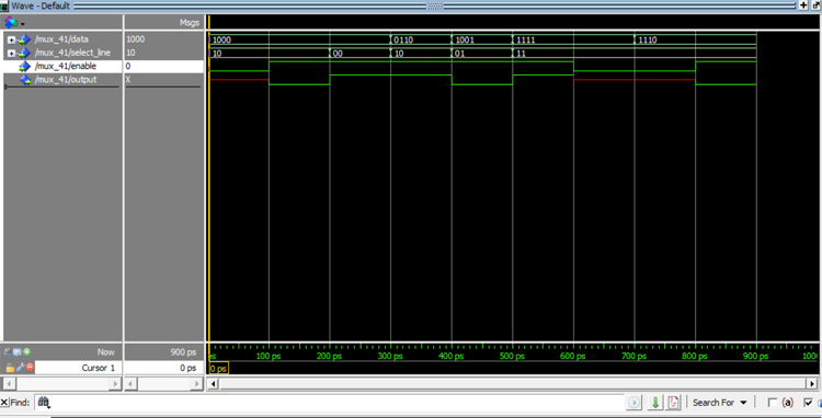
Move the cursor from 0-900 ps to track the corresponding values as tabulated in the table given below.
|
Timing(ps) |
Data(D3,D2,D1,D0) |
Selction Lines(S1,S0) |
Enable |
Y(output) |
|
0-100 |
1000 |
10 |
0 |
X |
|
100-200 |
1000 |
10 |
1 |
0 |
|
200-300 |
1000 |
00 |
1 |
1 |
|
300-400 |
0110 |
10 |
1 |
1 |
|
400-500 |
1001 |
01 |
1 |
0 |
|
500-600 |
1111 |
11 |
1 |
1 |
|
600-700 |
1111 |
11 |
0 |
X |
|
700-800 |
1110 |
11 |
0 |
X |
|
800-900 |
1110 |
11 |
1 |
0 |
From the table given above, we can infer that when the enable signal is “0” the output Y is “X” undefined. When the enable signal is “1” the corresponding inputs are mapped to the outputs with respect to the selection port values.
There is another electronic device that is exactly opposite to Multiplexer which is De-Multiplexer(Demux)
Are you curious to know what is a De-mux? Brace yourselves, let's learn about Demux.
What is a Demultiplexer (De-mux)?
DeMultiplexer is just the opposite of a Multiplexer. In simpler terms, it performs a reverse operation of the Multiplexer.
Let me give you an idea of what de-mux is about. Take a look at the image below.
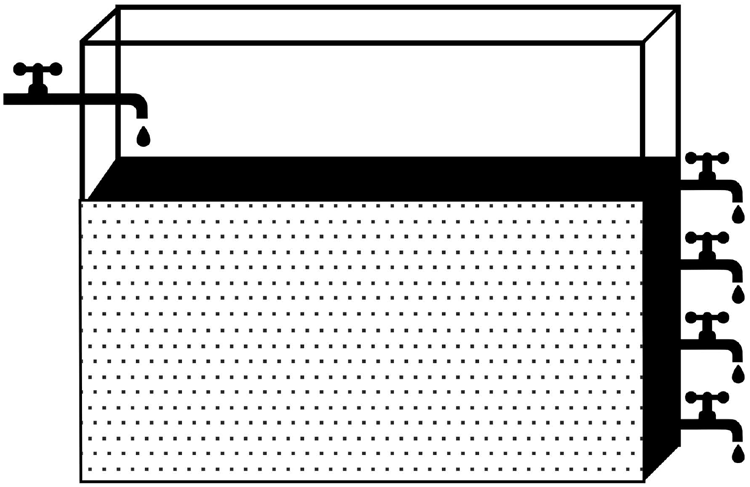
De-mux is similar to a water tank with one inlet and multiple outlets with gate valves. If we want the water to flow through a particular outlet pipe, we turn on the gate valve. Similarly, the selection lines act as a gate valve and direct the data to the particular single output port.
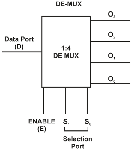
For a De-mux there is only one Input Port (i.e. Data Line), multiple output Ports, and selection lines. I have mentioned the general equation below for your reference.
No. of Input Ports (Data Ports): 1
Selection lines: n
Output Ports(N): 2n
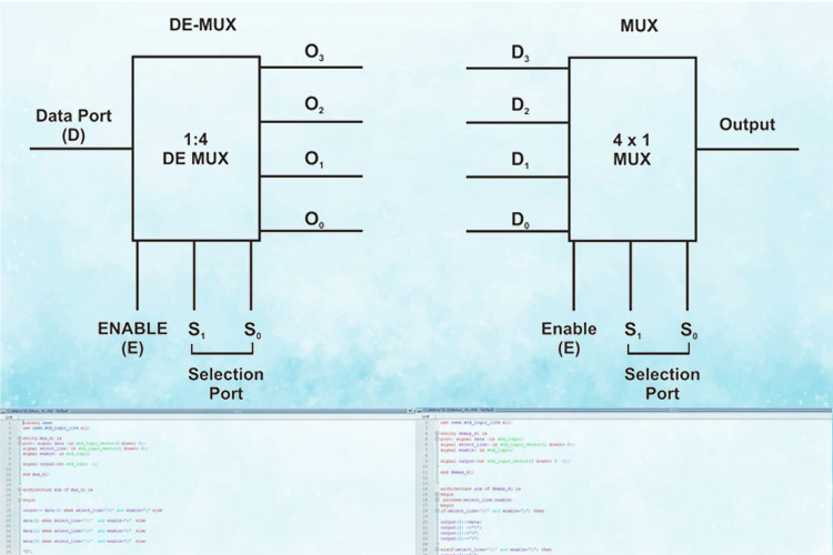
The schematic diagram and the Truth Table are as follows. The Data Line values can be either 0 or 1. I will represent the data line values with “D” so that we can keep track of the output.
|
Data Line(1/0) |
Enable |
Selection Lines(S1 S0) |
Output Ports( O3 O2 O1 O0) |
|
D |
0 |
X |
XXXX |
|
D |
1 |
00 |
D000 |
|
D |
1 |
01 |
0D00 |
|
D |
1 |
10 |
00D0 |
|
D |
1 |
11 |
000D |
|
|
|
|
|
Let's implement the same using VHDL in ModelSim. In general, it's denoted as 1:N De-mux
De-mux in VHDL: The code for the 1:4 Demux is given below. The Library and the entity declaration remain the same. The architecture definition has to be modified. Let's see what modification has to be done.
Library ieee;
use ieee.std_logic_1164.all;
entity demux_41 is
port( signal data :in std_logic;
signal select_line: in std_logic_vector(1 downto 0);
signal enable: in std_logic;
signal output:out std_logic_vector(3 downto 0  ));
end demux_41;
architecture sim of demux_41 is
begin
 process(select_line,enable)
begin
if(select_line="00" and enable='1') then
output(3)<=data;
output(2) <='0';
output(1)<='0';
output(0)<='0';
elsif(select_line="01" and enable='1') then
output(3)<='0';
output(2) <=data;
output(1)<='0';
output(0)<='0';
elsif (select_line="10" and enable='1') then
output(3)<='0';
output(2) <='0';
output(1)<=data;
output(0)<='0';
elsif (select_line="11" and enable='1') then
output(3)<='0';
output(2) <='0';
output(1)<='0';
output(0)<=data;
else
output(3)<='X';
output(2) <='X';
output(1)<='X';
output(0)<='X';
end if;
end process;
end sim;
The architecture declaration has to be modified. Since we have multiple scenarios if-else conditions are used to define the architecture. This is similar to the behavioral modelling method used in “how-to-design-a-simple-boolean logic-based-ic-using-VHDL-on-modelsim”. Refer to the above article for an overview of what is behavioral modelling and how VHDL code would look like for the behavioral modelling method.
process(select_line, enable): Since the output is dependent on selection ports and enable signals, its placed under process.
process(select_line,enable)
The rest of the code is nothing but declaring the if conditions and directing it to switch the outputs based on the specified values. The architecture segment of the VHDL code is given below for your reference.
architecture sim of demux_41 is

begin
 process(select_line,enable)
begin
if(select_line="00" and enable='1') then
output(3)<=data;
output(2) <='0';
output(1)<='0';
output(0)<='0';
elsif(select_line="01" and enable='1') then
output(3)<='0';
output(2) <=data;
output(1)<='0';
output(0)<='0';
elsif (select_line="10" and enable='1') then
output(3)<='0';
output(2) <='0';
output(1)<=data;
output(0)<='0';
elsif (select_line="11" and enable='1') then
output(3)<='0';
output(2) <='0';
output(1)<='0';
output(0)<=data;
else
output(3)<='X';
output(2) <='X';
output(1)<='X';
output(0)<='X';
end if;
end process;
end sim;
Now just copy-paste the Code for the De-mux, compile, simulate and verify the waveform values against the Truth Table.
For your reference, I have compiled and simulated the values in the waveform as shown below.
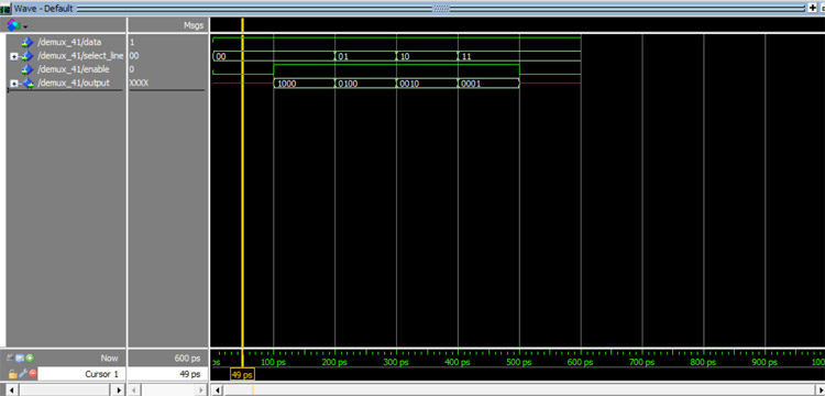
Move the cursor from 0-900 PS to track the corresponding values as tabulated in the table given below.
|
Timing(ps) |
Data(D=1/0) |
Selection Lines(S1,S0) |
Enable |
Output(O3 O2 O1 O0) |
|
0-100 |
1 |
00 |
0 |
XXXX |
|
100-200 |
1 |
00 |
1 |
1000 |
|
200-300 |
1 |
01 |
1 |
0100 |
|
300-400 |
1 |
10 |
1 |
0010 |
|
400-500 |
1 |
11 |
1 |
0001 |
|
500-600 |
1 |
11 |
0 |
XXXX |
For learning purposes, I have given the Data Value to be “1” so that we can keep track of where “1” is mapped to the Output Port.
From the table, we can infer that when the enable signal is “0” the output Y is “X” undefined. When the enable signal is “1” the corresponding inputs are mapped to the outputs with respect to the selection port values.
MUX:
Library ieee;
use ieee.std_logic_1164.all;
entity mux_41 is
port( signal data :in std_logic_vector(3 downto 0);
signal select_line: in std_logic_vector(1 downto 0);
signal enable: in std_logic;
signal output:out std_logic );
end mux_41;
architecture sim of mux_41 is
begin
output<= data(3) when select_line="00" and enable='1' else
data(2) when select_line="01" and enable='1' else
data(1) when select_line="10" and enable='1' else
data(0) when select_line="11" and enable='1' else
'X';
end sim;
Demux:
Library ieee;
use ieee.std_logic_1164.all;
entity demux_41 is
port( signal data :in std_logic;
signal select_line: in std_logic_vector(1 downto 0);
signal enable: in std_logic;
signal output:out std_logic_vector(3 downto 0 ));
end demux_41;
architecture sim of demux_41 is
begin
process(select_line,enable)
begin
if(select_line="00" and enable='1') then
output(3)<=data;
output(2) <='0';
output(1)<='0';
output(0)<='0';
elsif(select_line="01" and enable='1') then
output(3)<='0';
output(2) <=data;
output(1)<='0';
output(0)<='0';
elsif (select_line="10" and enable='1') then
output(3)<='0';
output(2) <='0';
output(1)<=data;
output(0)<='0';
elsif (select_line="11" and enable='1') then
output(3)<='0';
output(2) <='0';
output(1)<='0';
output(0)<=data;
else
output(3)<='X';
output(2) <='X';
output(1)<='X';
output(0)<='X';
end if;
end process;
end sim;

