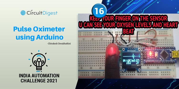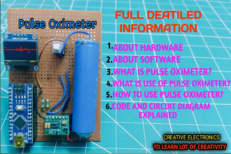
Hello friends, I am Chirukesh, and I am a YouTuber, this is a Pulse Oximeter that measures Oxygen Saturation blood also measures HeartBeat rate just using your finger. During this corona pandemic, a pulse Oximeter is very essential to measure heartbeat and oxygen levels. Friends you can also check with the medical PULSE OXIMETER, the reading will be the same, there will be no difference. In this pandemic period, many people can't buy the costly pulse oximeter nowadays. For them, this affordable price pulse oximeter is very best, this pulse oximeter price is around 899/-.

We will make this DIY Pulse Oximeter using Arduino Nano, you can check out our previously built Arduino projects. We have also worked on pulse sensor projects,
- How MAX30102 Pulse Oximeter and Heart Rate Sensor Works and how to Interface it with Arduino?
- Arduino based DIY Pulse Oximeter for measuring BPM
- IoT Based Heart Rate Monitor using MAX30100 Pulse Oximeter and ESP32
- Compact Arduino Based Pulse Oximeter Sensor Circuit
- How Does the Pulse Sensor Work and how to Interface it with Arduino?
Component Requirement for Pulse Oximeter

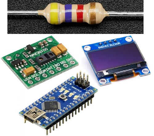
Project Used Hardware
- Arduino Nano,
- MAX30100 Pulse Sensor,
- SSD1306 Display,
- Wires,
- Bread Board,
- 4.7K RESISTER
Project Used Software
- Arduino IDE
Project Hardware Software Selection
Arduino NANO:- As you know that Arduino is a microcontroller-based open source electronic prototyping board that can be programmed with an easy-to-use Arduino IDE. The NANO is one of the most popular boards in the Arduino family and a great choice for beginners.
MAX30100:- This is MAX30100/30102 based Heart rate sensor. This works on a principle called photo-plethysmography, which means the changes in the volume of blood in an organ is measured by the changes in the intensity of the light passing through that organ hence the emitted light from the LED will be received by photosensor only when there is blood in the vein hence measuring the pulse. The output signal is further conditioned and filtered to give the final output. This pulse sensor module for Arduino provides biometric data which can be used to monitor anxiety levels, remote patient monitoring or exercise routines. It has an integrated temperature sensor for calibrating the temperature dependence of the pulse oximetry system. It also has a proximity detection function to reduce power consumption and visible light emission when the user’s finger is not on the sensor. It uses I2C communication to communicate with the microcontroller.
SSD1306:- OLED displays are popular for their low current consumption and bright viewing angles. This 0.96 Inch Monochrome (Blue) OLED display can be easily interfaced with microcontrollers like Arduino through I2C/IIC Communication. The 0.96" display is driven by the SSD1306 Display Driver IC. There are also other versions OLED display with a bigger display, different colors and a few of them can support SPI communication as well.
Arduino IDE - contains a text editor for writing code, a message area, a text console, a toolbar with buttons for common functions, and a series of menus. It connects to the Arduino and Genuino hardware to admin/upload programs and communicates with them.
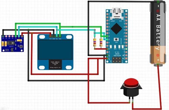
Circuit Diagram
#include <Wire.h>
#include "MAX30100_PulseOximeter.h"
#include <Adafruit_GFX.h>
#include <Adafruit_SSD1306.h>/
#define ENABLE_MAX30100 1
#define SCREEN_WIDTH 128 // OLED display width, in pixels
#define SCREEN_HEIGHT 32 // OLED display height, in pixels
// Declaration for an SSD1306 display connected to I2C (SDA, SCL pins)
// The pins for I2C are defined by the Wire-library.
// On an arduino UNO:       A4(SDA), A5(SCL)
// On an arduino MEGA 2560: 20(SDA), 21(SCL)
// On an arduino LEONARDO:   2(SDA),  3(SCL), ...
#define OLED_RESET    4 // 4 // Reset pin # (or -1 if sharing Arduino reset pin)
#define SCREEN_ADDRESS 0x3C///< See datasheet for Address; 0x3D for 128x64, 0x3C for 128x32
Adafruit_SSD1306 display(SCREEN_WIDTH, SCREEN_HEIGHT, &Wire, OLED_RESET);
#if ENABLE_MAX30100
#define REPORTING_PERIOD_MS     5000
// PulseOximeter is the higher level interface to the sensor
// it offers:
//  * beat detection reporting
//  * heart rate calculation
//  * SpO2 (oxidation level) calculation
PulseOximeter pox;
#endif
uint32_t tsLastReport = 0;
int xPos = 0;
// Callback (registered below) fired when a pulse is detected
void onBeatDetected()
{
  Serial.println("Beat!");
  heart_beat(&xPos);
}
void setup()
{
  Serial.begin(115200);
  Serial.println("SSD1306 128x64 OLED TEST");
  // SSD1306_SWITCHCAPVCC = generate display voltage from 3.3V internally
  if (!display.begin(SSD1306_SWITCHCAPVCC, SCREEN_ADDRESS)) {
    Serial.println(F("SSD1306 allocation failed"));
    for (;;); // Don't proceed, loop forever
  }
  // Show initial display buffer contents on the screen --
  // the library initializes this with an Adafruit splash screen.
  //display.display();
  display.clearDisplay();
  display.setTextSize(1);
  display.setTextColor(WHITE);
  display.setCursor(20, 18);
  // Display static text
  display.print("Pulse OxiMeter");
  int temp1 = 0;
  int temp2 = 40;
  int temp3 = 80;
  heart_beat(&temp1);
  heart_beat(&temp2);
  heart_beat(&temp3);
  xPos = 0;
  display.display();
  delay(2000); // Pause for 2 seconds
  display.cp437(true);
  display.clearDisplay();
  Serial.print("Initializing pulse oximeter..");
#if ENABLE_MAX30100
  // Initialize the PulseOximeter instance
  // Failures are generally due to an improper I2C wiring, missing power supply
  // or wrong target chip
  if (!pox.begin()) {
    Serial.println("FAILED");
    for (;;);
  } else {
    Serial.println("SUCCESS");
  }
  // The default current for the IR LED is 50mA and it could be changed
  //   by uncommenting the following line. Check MAX30100_Registers.h for all the
  //   available options.
  pox.setIRLedCurrent(MAX30100_LED_CURR_7_6MA);
  // Register a callback for the beat detection
  pox.setOnBeatDetectedCallback(onBeatDetected);
  display_data(0, 0);
#endif
}
void loop()
{
#if ENABLE_MAX30100
  // Make sure to call update as fast as possible
  pox.update();
  int bpm = 0;
  int spo2 = 0;
  // Asynchronously dump heart rate and oxidation levels to the serial
  // For both, a value of 0 means "invalid"
  if (millis() - tsLastReport > REPORTING_PERIOD_MS) {
    //Serial.print("Heart rate:");
    bpm = pox.getHeartRate();
    spo2 = pox.getSpO2();
    Serial.println(bpm);
    //Serial.print("bpm / SpO2:");
    Serial.println(spo2);
    //Serial.println("%");
    tsLastReport = millis();
    display_data(bpm, spo2);
  }
#endif
  drawLine(&xPos);
}
void display_data(int bpm, int spo2) {
display.fillRect(0, 18, 127, 15, BLACK);
  //if(bpm ==0 && spo2==0){
 //    display.setTextSize(1);
 // display.setTextColor(WHITE);
  //display.setCursor(0, 18);
  // Display static text
 // display.print("Fingure Out");
  //
}
  display.fillRect(0, 18, 127, 15, BLACK);
  display.setTextSize(1);
  display.setTextColor(WHITE);
  display.setCursor(0, 18);
  // Display static text
  display.print("BPM ");
  display.setTextSize(2);
  display.print(bpm);
  display.display();
  display.setTextSize(1);
  display.setTextColor(WHITE);
  display.setCursor(64, 18);
  // Display static text
  display.print("Spo2% ");
  display.setTextSize(2);
  display.println(spo2);
  display.display();
}
void drawLine(int *x_pos) {
  // Draw a single pixel in white
  display.drawPixel(*x_pos, 8, WHITE);
  display.drawPixel((*x_pos)++, 8, WHITE);
  display.drawPixel((*x_pos)++, 8, WHITE);
  display.drawPixel((*x_pos)++, 8, WHITE);
  display.drawPixel((*x_pos), 8, BLACK);  // -----
  //Serial.println(*x_pos);
  display.fillRect(*x_pos, 0, 31, 16, BLACK);
  display.display();
  //delay(1);
  if (*x_pos >= SCREEN_WIDTH) {
    *x_pos = 0;
  }
}
void heart_beat(int *x_pos) {
  /************************************************/
  //display.clearDisplay();
  display.fillRect(*x_pos, 0, 30, 15, BLACK);
  // Draw a single pixel in white
  display.drawPixel(*x_pos + 0, 8, WHITE);
  display.drawPixel(*x_pos + 1, 8, WHITE);
  display.drawPixel(*x_pos + 2, 8, WHITE);
  display.drawPixel(*x_pos + 3, 8, WHITE);
  display.drawPixel(*x_pos + 4, 8, BLACK); // -----
  //display.display();
  //delay(1);
  display.drawPixel(*x_pos + 5, 7, WHITE);
  display.drawPixel(*x_pos + 6, 6, WHITE);
  display.drawPixel(*x_pos + 7, 7, WHITE); // .~.
  //display.display();
  //delay(1);
  display.drawPixel(*x_pos + 8, 8, WHITE);
  display.drawPixel(*x_pos + 9, 8, WHITE); // --
  //display.display();
  //delay(1);
  /******************************************/
  display.drawPixel(*x_pos + 10, 8, WHITE);
  display.drawPixel(*x_pos + 10, 9, WHITE);
  display.drawPixel(*x_pos + 11, 10, WHITE);
  display.drawPixel(*x_pos + 11, 11, WHITE);
  //display.display();
  //delay(1);
  /******************************************/
  display.drawPixel(*x_pos + 12, 10, WHITE);
  display.drawPixel(*x_pos + 12, 9, WHITE);
  display.drawPixel(*x_pos + 12, 8, WHITE);
  display.drawPixel(*x_pos + 12, 7, WHITE);
  //display.display();
  //delay(1);
  display.drawPixel(*x_pos + 13, 6, WHITE);
  display.drawPixel(*x_pos + 13, 5, WHITE);
  display.drawPixel(*x_pos + 13, 4, WHITE);
  display.drawPixel(*x_pos + 13, 3, WHITE);
  //display.display();
  //delay(1);
  display.drawPixel(*x_pos + 14, 2, WHITE);
  display.drawPixel(*x_pos + 14, 1, WHITE);
  display.drawPixel(*x_pos + 14, 0, WHITE);
  display.drawPixel(*x_pos + 14, 0, WHITE);
  //display.display();
  //delay(1);
  /******************************************/
  display.drawPixel(*x_pos + 15, 0, WHITE);
  display.drawPixel(*x_pos + 15, 1, WHITE);
  display.drawPixel(*x_pos + 15, 2, WHITE);
  display.drawPixel(*x_pos + 15, 3, WHITE);
  //display.display();
  //delay(1);
  display.drawPixel(*x_pos + 15, 4, WHITE);
  display.drawPixel(*x_pos + 15, 5, WHITE);
  display.drawPixel(*x_pos + 16, 6, WHITE);
  display.drawPixel(*x_pos + 16, 7, WHITE);
  //display.display();
  //delay(1);
  display.drawPixel(*x_pos + 16, 8, WHITE);
  display.drawPixel(*x_pos + 16, 9, WHITE);
  display.drawPixel(*x_pos + 16, 10, WHITE);
  display.drawPixel(*x_pos + 16, 11, WHITE);
  //display.display();
  //delay(1);
  display.drawPixel(*x_pos + 17, 12, WHITE);
  display.drawPixel(*x_pos + 17, 13, WHITE);
  display.drawPixel(*x_pos + 17, 14, WHITE);
  display.drawPixel(*x_pos + 17, 15, WHITE);
  //display.display();
  //delay(1);
  display.drawPixel(*x_pos + 18, 15, WHITE);
  display.drawPixel(*x_pos + 18, 14, WHITE);
  display.drawPixel(*x_pos + 18, 13, WHITE);
  display.drawPixel(*x_pos + 18, 12, WHITE);
  //display.display();
  //delay(1);
  display.drawPixel(*x_pos + 19, 11, WHITE);
  display.drawPixel(*x_pos + 19, 10, WHITE);
  display.drawPixel(*x_pos + 19, 9, WHITE);
  display.drawPixel(*x_pos + 19, 8, WHITE);
  //display.display();
  //delay(1);
  /****************************************************/
  display.drawPixel(*x_pos + 20, 8, WHITE);
  display.drawPixel(*x_pos + 21, 8, WHITE);
  //display.display();
  //delay(1);
  /****************************************************/
  display.drawPixel(*x_pos + 22, 7, WHITE);
  display.drawPixel(*x_pos + 23, 6, WHITE);
  display.drawPixel(*x_pos + 24, 6, WHITE);
  display.drawPixel(*x_pos + 25, 7, WHITE);
  //display.display();
  //delay(1);
  /************************************************/
  display.drawPixel(*x_pos + 26, 8, WHITE);
  display.drawPixel(*x_pos + 27, 8, WHITE);
  display.drawPixel(*x_pos + 28, 8, WHITE);
  display.drawPixel(*x_pos + 29, 8, WHITE);
  display.drawPixel(*x_pos + 30, 8, WHITE); // -----
  *x_pos = *x_pos + 30;
  display.display();
  delay(1);
}


Hello,
I'm a school student and I want to make this project.
But I have max30102 Pulse sensor and Arduino pro micro.
So, does it need change? what I have to change?
Please help me