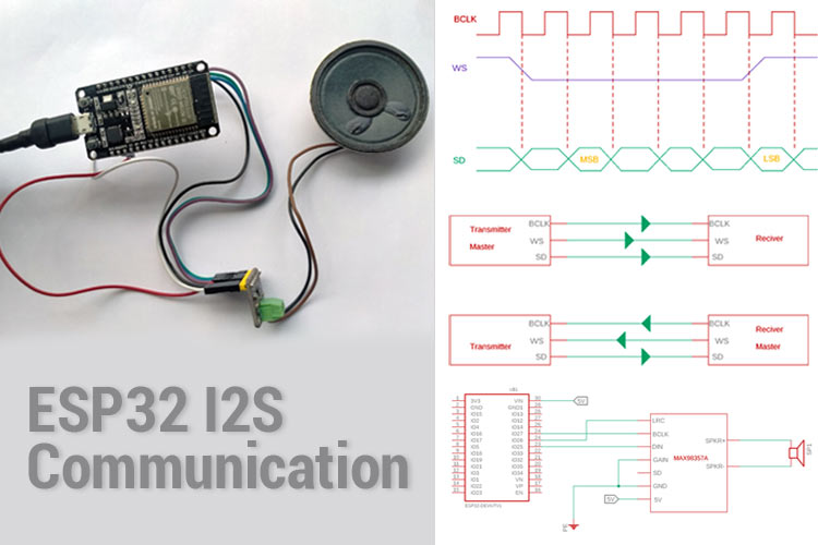
I2S is an Inter-IC Sound protocol that is used mainly to transmit or receive the audio data in a synchronous serial port between two devices. There are many applications where audio communication is required in digital devices such as adding a microphone or adding a speaker output to play some audio.
There are multiple Audio protocols available in electronics where audio codecs, DAC (In case of Audio output), or ADC (In case of Audio input) are used. One of the simplest and probably the best ways is to use the I2S protocol that uses simple pin configurations and communicates between two digital audio devices.
The I2S protocol is designed by Philips Semiconductor, now NXP Semiconductors and it is widely used in different microcontrollers, codecs, audio modules, microphones that use this protocol to communicate the data. We have previously used I2S communication to build an Internet Radio using ESP32, you can also check that project out if interested.
Let's Explore what are the key points and how this I2S Protocol works in microcontroller units.
I2S 3-Wire Connection
The I2S protocol uses three wires for communication. The connection between the transmitter and the receiver is shown below.

Word Select (WS) or Frame Select (FS) wire:
Since the I2S protocol uses both stereo operations, the channel left or Right can be selected using the WS or Word Select pin. Generally, If the WP pin is in Low state, Channel 1 or the Left channel is selected, on the other hand, if the WS pin is in the High State, the right channel is used.
To summarise:
If WS pin = 0 then Channel 1 or left channel is activated
If WS pin = 1 then Channel 2 or Right channel is activated
Irrespective of the above channel selection pin, the I2S protocol uses two additional pins that are most common in any serial interface.
Serial Data Pin or SD:
This second line of the I2S communication protocol is the Serial Data or the SD Pin that carries the data signal. The transmission of data through this line uses the 2 complements method.
In I2S data transfer, the most significant bit (MSB) is transferred first making it an MSB first data line. This is done for an obvious reason. In I2S, the data can be in different word lengths that are transmitted from the transmitter to the receiver.
Thus, if the MSB is first transmitted, there would be no dependencies for the transmitter and the receiver to know how many bits are transferred or coming in.
This opens a new problem, since the receiver and the transmitter do not know the word length, it becomes difficult to match the data since it can be lost during data transmission due to noise and other factors. This is solved using the WS pin or WS line.
If the WS of the receiver is greater than the WS of the transmitter, the word is truncated where the least significant data bits are set to 0. If the WS of the receiver is less than the WS of the transmitter, the bits after the LSB are ignored.
Bit clock line or BCLK:
The last and most important pin of the I2S communication is the Serial Clock (SCK) also called the bit clock line (BCLK). As suggested in the name, it is a clock pin and it is important in the serial data communication protocol.
It is used to get all components on the same cycle. This BCLK line frequency is dependent on the sample rate, Bits per channel, and the number of channels it is using.
The formula that can be used to get the frequency is:
Frequency = Sample Rate x Bits per channel x Number of channels.
For an example:
Sample rate: 44.1 kHz
Bits per channel: 8
Number of channels: 2 [Stereo]
Therefore, the serial clock has a frequency of 44.1 kHz * 8 * 2 = 705 kHz.
I2S Timing Diagram
In the below diagram, the timing sequence is shown:
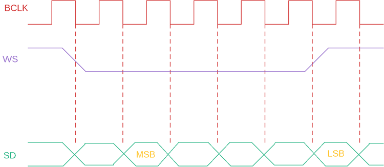
In the above timing diagram, three lines are shown, BCLK, WS, SD. The BCLK will provide the required clock cycles for the I2S line. The WS is changing its state from the Right channel to the Left channel.
The data is transmitted over the I2S and it is sent on every clock cycle. The WS pin changes its state from one channel to another channel before one clock cycle of the I2S data line starts transmitting the MSB. This is due to the receiver requiring time to store the word that is previously sent and clear the register.
I2S Controller Features in ESP32
Since we are familiar with I2S, let's see how this can be used in a microcontroller. ESP32 is a widely popular low-cost, WiFi and Bluetooth enabled 32-Bit microcontroller unit, that supports I2S features.
Below, is a comprehensive list of I2S controller features of ESP32 I2S Driver.
- The ESP32 I2S controller driver could operate as a system master or slave.
- It is also capable of acting as a transmitter or receiver in the I2S Bus.
- ESP32 has a dedicated DMA controller that could stream sample data without being dependent on the CPU to copy and check each data sample.
- ESP32 I2S peripherals also support LCD. In this mode, the I2S data starts communicating over a parallel bus. It is required in some LCDs and camera modules.
In the LCD mode, the I2S controller could operate in the following modes.
- LCD as master transmitting mode.
- Camera as slave receiving mode.
- ADC/DAC mode.
To start the I2S program and how to write codes for the I2C, let's select an I2S module and make an application.
NOKIA Tone Generator using I2S
Let's connect a speaker in the I2S protocol and generate the iconic NOKIA tune using the ESP32 I2S.
However, since the speaker is an analog device and to drive this, we need an I2S supported amplifier; we chose to use a MAX98357A, I2S based Mono Amplifier module.
The below image is showing the pinout of the module.
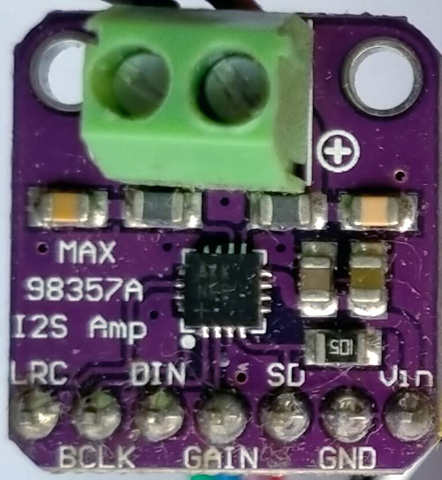
Three important pins of the module are BCLK, DIN, and LRC. The DIN is the data input pin which is the same as the SD and the LRC is the Left-Right Channel selection pin, the same as the WS.
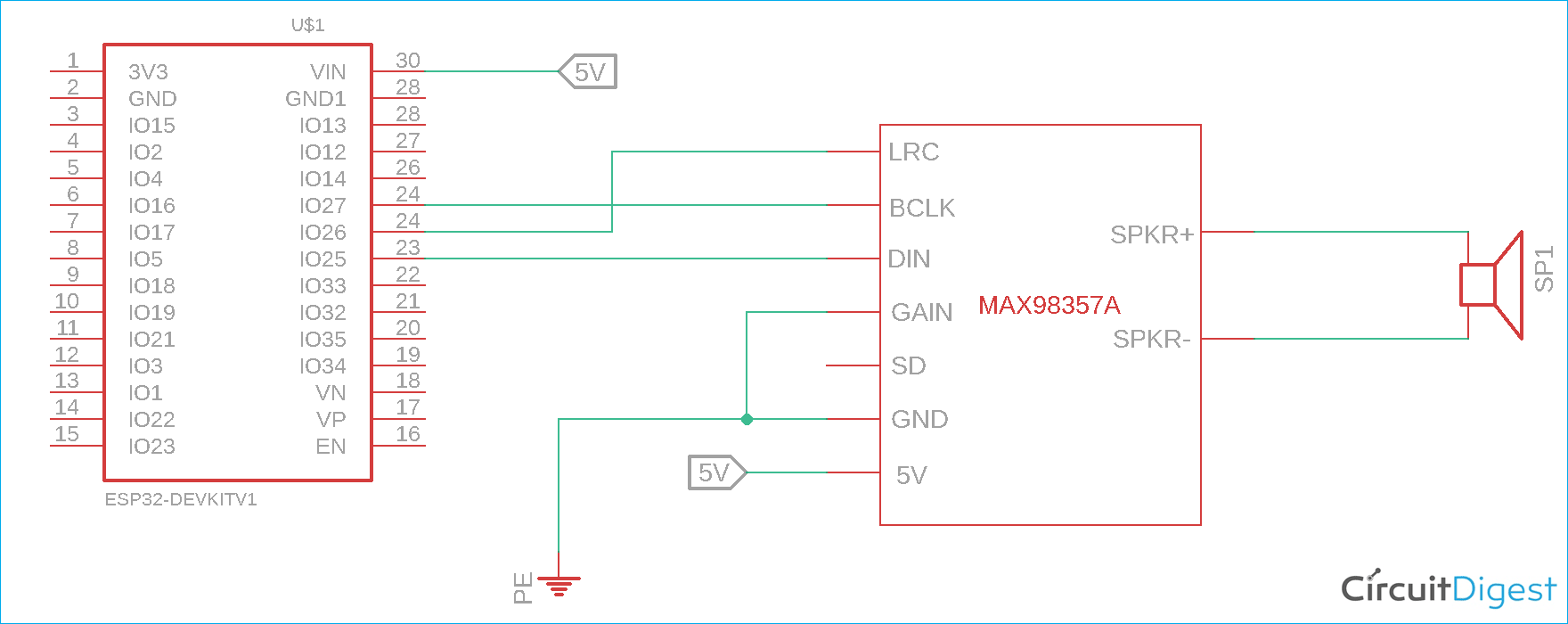
The Circuit will go like this.
BCLK, Word Select, and the Serial Data pins are selected as the below pin.
- BCLK pin of I2S = BCLK Pin of the Module = ESP32 Pin 27
- Word Select pin of I2S = LRC Pin of the Module = ESP32 Pin 26
- Serial Data pin of I2S = DIN Pin of the Module = ESP32 Pin 25
The schematic can be seen below.
I2S Sample Code for ESP32
Well, to run the code, the sampleaac.h header file holds the aac of the Nokia tune that is converted to the HEX format.
The header file has a format like this.
const unsigned char sampleaac[] PROGMEM = { 0xFF, 0xF9, 0x5C, 0x80, 0x2E, …………. 0x00, 0x00, 0x00, 0x00, 0x00, 0x00, 0x00, 0x00, 0x00,
0xF2
};
All header files are included first
#include "AudioGeneratorAAC.h"
#include "AudioOutputI2S.h"
#include "AudioFileSourcePROGMEM.h"
#include "sampleaac.h"
We are using the audio generator AAC library that uses the I2S protocol to generate the audio. This is available in the below GitHub.
https://github.com/earlephilhower/ESP8266Audio
After that, the pins are set as per the pin diagram provided before.
#define Bit_Clock_BCLK 27
#define Word_Select_WS 26
#define Serial_Data_SD 25
Then in the setup, the I2S device pinout is set on the I2S driver.
  in = new AudioFileSourcePROGMEM(sampleaac, sizeof(sampleaac));
  aac = new AudioGeneratorAAC();
  out = new AudioOutputI2S();
  out -> SetGain(GAIN);
  out -> SetPinout(Bit_Clock_BCLK,Word_Select_WS,Serial_Data_SD);
  aac->begin(in, out);
}
The while loop is playing the audio on the sample AAC.
void loop(){
  if (aac->isRunning()) {
            aac->loop();
  } else {
            aac -> stop();
            Serial.printf("Sound Generator\n");
            delay(1000);
  }
}
Playing Nokia Tune on ESP32 using I2S Communication
Now that we know how I2S communication on ESP32 works, we can make the connections, upload the code and play the test audio. For this article, I have played the Nokia tune for example. As we can see, all the things are connected properly and are ready for testing.
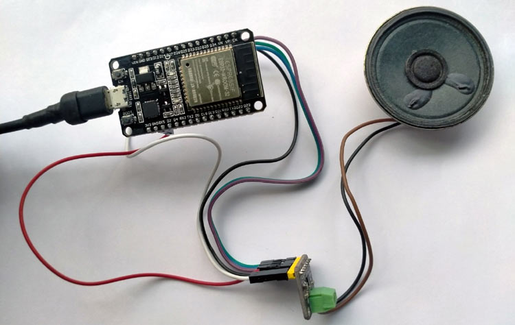
The complete working of this project can be found in the video below. Hope this article helps you to use ESP32 I2S Audio for all your future projects. If you have any questions, you can leave them in the comment section below or post them on our forums.
#include "AudioGeneratorAAC.h"
#include "AudioOutputI2S.h"
#include "AudioFileSourcePROGMEM.h"
#include "sampleaac.h"
#define Bit_Clock_BCLK 27
#define Word_Select_WS 26
#define Serial_Data_SD 25
#define GAIN 0.125
AudioFileSourcePROGMEM *in;
AudioGeneratorAAC *aac;
AudioOutputI2S *out;
void setup(){
Serial.begin(115200);
in = new AudioFileSourcePROGMEM(sampleaac, sizeof(sampleaac));
aac = new AudioGeneratorAAC();
out = new AudioOutputI2S();
out -> SetGain(GAIN);
out -> SetPinout(Bit_Clock_BCLK,Word_Select_WS,Serial_Data_SD);
aac->begin(in, out);
}
void loop(){
if (aac->isRunning()) {
aac->loop();
} else {
aac -> stop();
Serial.printf("Sound Generator\n");
delay(1000);
}
}

