FSM (Finite State Machines) is a simple state machine or a mathematical model of computation. Each FSM has a finite number of states, inputs, outputs, and rules to change from one state to the other state. FSM is defined by a finite number of states and switches from one state to the other when specific input is given to the state machine. FSM’s are widely used in vending machines, traffic lights, security locks, and software algorithms. In this article, you can learn about the basics of FSM and implementing an FSM design in VHDL using ModelSim. If you are new to VHDL refer to our previous tutorials on VHDL.
What is an FSM?
FSM (Finite State Machine) by the name is defined as a state machine that has a finite number of states. The example for the states can be A, B, C, and D. Each FSM has input and output values. These states keep changing from one to the other when input is given and produces a corresponding output.
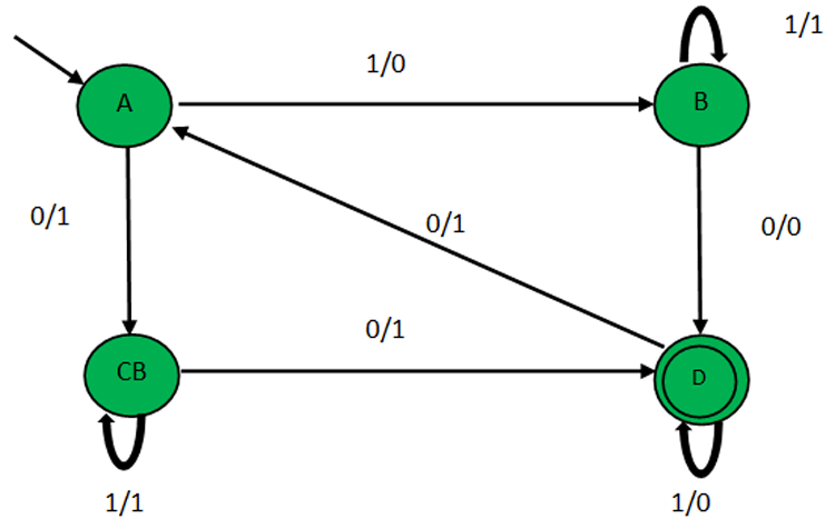
Let me explain with a simple FSM Design as shown below.

The green circles indicate the states of the FSM. So, the available states are A, B, C, D. The  near the state circle A indicates that ‘A’ is the initial state. The double circled state, D indicates that D is the last state of the FSM. We can see that arrows are running between the available states with 1’s and 0’s. These are the inputs and outputs that determine where the next state should shift to and the corresponding outputs.

Always remember that these arrows form the rule for transition. The notations above the arrows left side of the slash represent input, right side to slash represent the output. For example, if it is “1/0” 1 represents input, and 0 represents output.
FSM’s have a state transition table from which we can calculate the next state. The Transition Table is given below.
NOTE: Always look at the arrows pointing outwards from the state to predict the next state.
|
Present State |
Input |
Next State |
Output |
|
A |
1 |
B |
0 |
|
A |
0 |
C |
1 |
|
B |
0 |
D |
0 |
|
B |
1 |
B |
1 |
|
C |
0 |
D |
1 |
|
C |
1 |
C |
1 |
|
D |
1 |
D |
0 |
|
D |
0 |
A |
1 |
Let us examine the State Transition Table and the State Diagram for a better understanding. If the present state is A and the input is “1”, look for the arrows pointing outwards of state A which has input “1”. If so, the next state is B and the output is 0. Now, the present state gets updated as “B”. Now lookup for the present state “B”, says input is 0 the next state is “D”. So on, the state keeps changing.
Moreover, FSM has a clock and reset signal too. If the reset =1 or reset is active, it will go back to the initial state which is “A” (i.e. starting state)
Now, that we know the basics of FSM, let's implement the same design in VHDL using ModelSim.
Brace yourself let's learn how to implement the same design in VHDL using ModelSim.
VHDL Code for FSM:
At first, I will give the full code and then break it down into smaller snippets for better understanding.
library IEEE;
use IEEE.STD_LOGIC_1164.ALL;
entity fsm is
    Port ( reset : in  STD_LOGIC;
input : in  STD_LOGIC;
output : out  STD_LOGIC;
clk : in  STD_LOGIC);
end fsm;
architecture Behavioral of fsm is
type state_available is (A,B,C,D);  --type of state machine.
signal present_state,next_state: state_available;
begin
process (clk,reset)
begin
 if (reset='1') then
present_state<= A;  --default state on reset.
elsif (rising_edge(clk)) then
present_state<= next_state;   --state change.
end if;
end process;
process (present_state,input)
begin
  case present_state is
     when A =>        --when current state is "A"
if(input ='0') then
      output <= '1';
next_state<= C;
    else
      output <= '0';
next_state<= B;
     end if;
     when B =>        --when current state is "B"
if(input ='0') then
      output <= '0';
next_state<= D;
    else
      output <= '1';
next_state<= B;
    end if;
    when C =>       --when current state is "C"
if(input ='0') then
      output <= '1';
next_state<= D;
    else
      output <= '1';
next_state<= C;
    end if;
  when D =>         --when current state is "D"
if(input ='0') then
      output <= '1';
next_state<= A;
    else
      output <= '0';
next_state<= D;
    end if;
  end case;
end process;
end Behavioral;
At first, the libraries are imported and the entity is declared with the label “fsm” along with the input, output, clock, and reset port/signals.
library IEEE;
use IEEE.STD_LOGIC_1164.ALL;
entity fsm is
    Port ( reset : in  STD_LOGIC;
input : in  STD_LOGIC;
output : out  STD_LOGIC;
clk : in  STD_LOGIC);
end fsm;
The architecture is defined and labelled with the name “Behavioral”. We use “type” data to define the available states in the FSM. “type” is an enumerated data type that can list the possible values for that particular variable.
For example, state_available can have only the values A, B, C, D. As the present and the next state can be only A, B, C, D the present and the next state signal are mapped to the “type state_available” where “state_available” is the label name for type.
architecture Behavioral of fsm is
type state_available is (A,B,C,D);  --type of state machine.
signal present_state,next_state: state_available;
Once this is done, we have to mention the condition for the reset value. Since, the ‘if’ conditions are based on the clock and reset. They have to be processed, hence we declare “process(clk,reset)”.
If reset=1, then the present state is assigned/initialized as A, if not, the present state is updated to the next state.
Rising edge of a clock means the point where the signal transits from 0 to 1.
begin
process (clk,reset)
begin
 if (reset='1') then
present_state<= A;  --default state on reset.
elsif (rising_edge(clk)) then
present_state<= next_state;   --state change.
end if;
end process;
The segment is to define the transition state table. Since, the transition state depends on the input and the present state they should be processed first. Hence “process(present_state,input)” is declared.
process (present_state,input)
As there are many cases/scenarios where using the “case” statement associated with the present state. The conditions A, B, C, D being the present state the state change, and the output conditions are assigned.
begin
  case present_state is
     when A =>        --when current state is "A"
if(input ='0') then
      output <= '1';
next_state<= C;
    else
      output <= '0';
next_state<= B;
     end if;
     when B =>        --when current state is "B"
if(input ='0') then
      output <= '0';
next_state<= D;
    else
      output <= '1';
next_state<= B;
    end if;
    when C =>       --when current state is "C"
if(input ='0') then
      output <= '1';
next_state<= D;
    else
      output <= '1';
next_state<= C;
    end if;
  when D =>         --when current state is "D"
if(input ='0') then
      output <= '1';
next_state<= A;
    else
      output <= '0';
next_state<= D;
    end if;
  end case;
end process;
end Behavioral;
Just compile the above-given code for simulating the FSM. Refer to “Implementation of basic logic gates using VHDL in ModelSim”
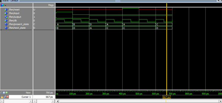
I have simulated the above code and the following waveform for the FSM is given below.
|
Timing(ps) |
Present State |
Reset |
Input |
Next State |
Output |
|
0-100 |
A |
U |
1 |
B |
0 |
|
100-200 |
B |
U |
0 |
D |
0 |
|
200-300 |
D |
U |
0 |
A |
1 |
|
300-400 |
A |
U |
0 |
C |
1 |
|
400-500 |
A |
1 |
0 |
C |
1 |
|
500-600 |
A |
U |
0 |
C |
1 |
|
600-700 |
C |
U |
0 |
D |
1 |
Move the cursor along the waveform to notice the change in the states and the output. There might be some delays due to the clock, but it will get updated in the next clock cycle.
So, that was all about the Finite State Machine Designs and its implementation in VHDL using ModelSim.
library IEEE;
use IEEE.STD_LOGIC_1164.ALL;
entity fsm is
Port ( reset : in STD_LOGIC;
input : in STD_LOGIC;
output : out STD_LOGIC;
clk : in STD_LOGIC);
end fsm;
architecture Behavioral of fsm is
type state_available is (A,B,C,D); --type of state machine.
signal present_state,next_state: state_available;
begin
process (clk,reset)
begin
if (reset='1') then
present_state <= A; --default state on reset.
elsif (rising_edge(clk)) then
present_state <= next_state; --state change.
end if;
end process;
process (present_state,input)
begin
case present_state is
when A => --when current state is "A"
if(input ='0') then
output <= '1';
next_state <= C;
else
output <= '0';
next_state <= B;
end if;
when B => --when current state is "B"
if(input ='0') then
output <= '0';
next_state <= D;
else
output <= '1';
next_state <= B;
end if;
when C => --when current state is "C"
if(input ='0') then
output <= '1';
next_state <= D;
else
output <= '1';
next_state <= C;
end if;
when D => --when current state is "D"
if(input ='0') then
output <= '1';
next_state <= A;
else
output <= '0';
next_state <= D;
end if;
end case;
end process;
end Behavioral;


