A 4x4 membrane keypad is a compact and a cost-effective input device that is commonly used in a variety of electronics projects. It consists of 16 buttons arranged in a 4x4 grid and is covered with a flexible membrane that protects the buttons and ensures their durability. In this blog, we'll go over how to interface a 4x4 membrane keypad with an Arduino microcontroller. By the end of this tutorial, you'll be able to read the state of the keypad and determine which key has been pressed.
We'll cover the required hardware, wiring diagram, and code required to get your membrane keypad up and running. Whether you're a beginner or an experienced maker, this tutorial is designed to be a simple and straightforward guide to interfacing a 4x4 membrane keypad with an Arduino. Prior to this, we have also done interfacing of 4x4 membrane keypad with PIC microcontroller.
4x4 Membrane Keypad Pinout
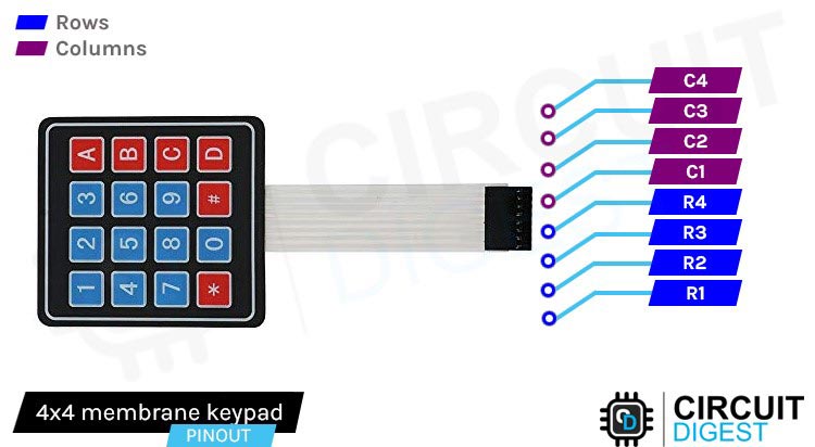
The pinout of a 4x4 membrane keypad typically consists of 8 pins, 4 for the columns and 4 for the rows. The pin configuration may vary depending on the specific keypad model, but the general idea is that the columns are connected to the Arduino’s input pins and the rows are connected to the Arduino’s output pins.
It's important to verify the pinout of your specific 4x4 membrane keypad before connecting it to the Arduino. You may also need to adjust the pin connections in the code to match your keypad's pinout.
Inside a 4 x 4 Membrane Keypad
1. Substrate: A non-conductive material, such as plastic, that serves as the base for the keypad.
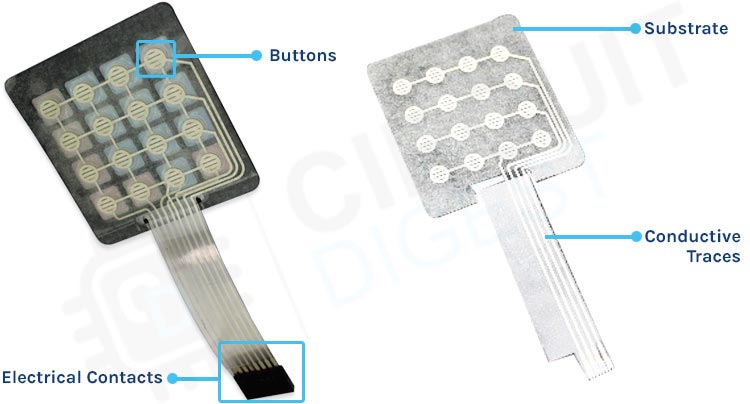
2. Conductive traces: thin metal wires or stripes, typically made of copper or silver, that run between the buttons and the microcontroller.
3. Buttons: Flexible buttons made of silicone or similar material, that completes an electrical circuit when pressed and connects to the conductive traces.
4. Adhesive: A layer of adhesive material, such as glue or tape, that is used to attach the buttons to the substrate.
5. Cover layer: A clear layer that covers the buttons and protects the keypad from damage and wear.
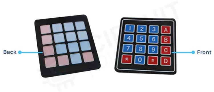
6. Electrical contacts: Connections between the keypad and the microcontroller, usually made of metal pins, that allow the microcontroller to read the state of the buttons.
Commonly asked questions about 4x4 Membrane Keypad
What does a 4x4 membrane keypad do?
The specific use of a 4 x 4 membrane keypad can vary depending on the application. For example, it could be used for numeric or alphanumeric data entry, menu navigation, or as a simple control interface for a device. Its compact size and low cost make it a popular choice for many applications where a small and simple input device is needed.
What is the size of a 4x4 membrane keypad?
The size of a 4x4 membrane keypad can vary, but a typical size for a standard 4x4 membrane keypad is around 70mm x 77mm (2.75 inches x 3 inches). However, the size can depend on the manufacturer and specific model of the keypad. Some may be smaller or larger depending on the requirements of the application or the preferences of the designer. Additionally, the thickness of a membrane keypad can also vary, typically ranging from 0.5mm to 1.5mm.
Where can I buy a membrane keypad?
There are lots of membrane keypad sellers in India but we would recommend quartz components because of their fast delivery and excellent after-sales service.
How does a Membrane Keypad work?
When a button is pressed on a membrane keypad, it completes an electrical circuit and sends a signal to the microcontroller. The microcontroller is a computer chip that processes the input from the buttons and determines which key has been pressed.
All rows and columns in the keypad are wired together in order to reduce the number of i/o pins. Normally connecting 16 push buttons like that would require 17 I/O pins. 16 for push buttons and 1 for ground.
By connecting rows and columns together only 8 pins are required. this specific technique is called as multiplexing.
The 4x4 keypad has 4 rows and 4 columns so it has total of 4+4 =8 output pins
When a button is pressed on a membrane keypad, it connects one row to one column, allowing a small electrical current to flow between them. This creates an electrical circuit that can be detected by the microcontroller, which can then determine which button has been pressed based on the combination of the connected row and column. The button press creates a change in voltage or current, which the microcontroller can detect and interpret as an input signal. The keypad may use a scanning method where the microcontroller sends a series of pulses to each row and measures the voltage on each column to determine which button has been pressed.
for instance, when key '2' is pressed. row 1 and column 2 are connected and microcontroller know that '2' is pressed
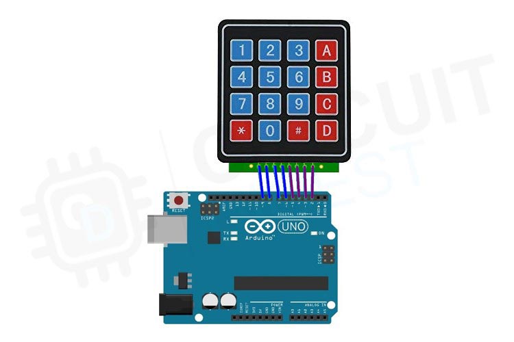
Circuit Diagram of Interfacing Membrane Keypad with Arduino Uno
Connection of Arduino with 4x4 keypad is quite simple. Connect the 4 columns of the keypad to digital pins 4, 5, 6, and 7 on the Arduino, and the 4 rows to digital pins 8, 9, 10, and 11. This can be done by soldering wires to the keypad or by using connectors or headers to make the connections.
Arduino Code
This code will print whatever is pressed on the serial monitor to the keypad
#include <Keypad.h>
const byte ROWS = 4; //four rows
const byte COLS = 4; //four columns
char keys[ROWS][COLS] = {
  {'1','2','3','A'},
  {'4','5','6','B'},
  {'7','8','9','C'},
  {'*','0','#','D'}
};
byte rowPins[ROWS] = {9, 8, 7, 6}; //connect to the row pinouts of the keypad
byte colPins[COLS] = {5, 4, 3, 2}; //connect to the column pinouts of the keypad
//Create an object of keypad
Keypad keypad = Keypad( makeKeymap(keys), rowPins, colPins, ROWS, COLS );
void setup(){
  Serial.begin(9600);
}
void loop(){
  char key = keypad.getKey();// Read the key
  // Print if key pressed
  if (key){
    Serial.print("Key Pressed : ");
    Serial.println(key);
  }
}
Explanation of the Arduino and Membrane Keypad Interfacing Code
#include <Keypad.h>
This line imports the Keypad library, which provides functions to interface a keypad with an Arduino but before including it in the code itself you need to install the library in the Arduino IDE
Go to sketch>include library > manage libraries
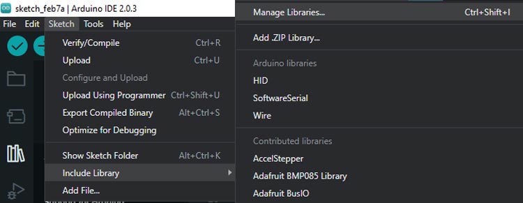
Enter ‘keypad’ in the search box and look for Keypad by Mark Stanley, Alexander Brevig. Click on the install button there.

const byte ROWS = 4; //four rows
const byte COLS = 4; //four columns
The constants ROWS and COLS are defined to store the number of rows and columns of the keypad, which is 4 in this case.
char keys[ROWS][COLS] = {
  {'1','2','3','A'},
  {'4','5','6','B'},
  {'7','8','9','C'},
  {'*','0','#','D'}
};
byte rowPins[ROWS] = {9, 8, 7, 6}; //connect to the row pinouts of the keypad
byte colPins[COLS] = {5, 4, 3, 2}; //connect to the column pinouts of the keypad
Next, a two-dimensional character array named "keys" is created to store the keypad button labels. The rowPins and colPins arrays are used to store the pin numbers connected to the rows and columns of the keypad, respectively.
//Create an object of keypad
Keypad keypad = Keypad( makeKeymap(keys), rowPins, colPins, ROWS, COLS );
The Keypad object is created using the makeKeymap() function and passing in the "keys" array, "rowPins" array, "colPins" array, and the number of rows and columns.
void setup(){
  Serial.begin(9600);
}
void loop(){
  char key = keypad.getKey();// Read the key
  // Print if key pressed
  if (key){
    Serial.print("Key Pressed : ");
    Serial.println(key);
  }
}
In the setup() function, the serial communication is initiated with a baud rate of 9600.
In the loop() function, the getKey() method is used to read the key press from the keypad, and the key press is printed to the serial monitor using the Serial.println() function if a key is pressed.
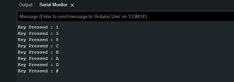
After loading the sketch in your arduino, and then open the serial monitor at 9600 baud rate. Now press some keys on the keypad and you will notice that those key values are been displayed on the serial monitor.
Projects using 4 X 4 Membrane keypad
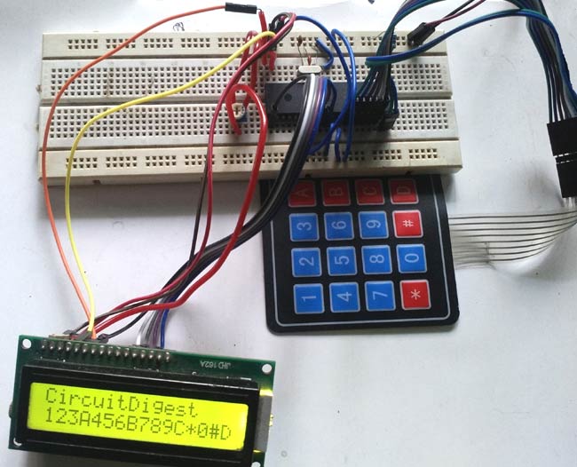
Imagine a world where every input is at your fingertips. With a 4x4 matrix keypad and an 8051 microcontroller, that world is within reach. From secure password input systems to custom menu interfaces, the possibilities are endless. Join us as we explore the power of this simple yet effective input device and the versatile microcontroller that brings it to life.
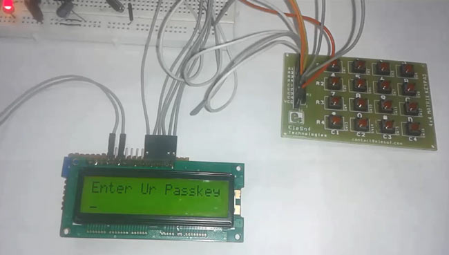
Secure your space with a digital code lock powered by the versatile 8051 microcontroller. With the ability to customize your lock's code and maybe in future add features such as timers and alarms, you can create a robust and reliable security system. The 8051's processing power and low power consumption make it an ideal choice for this type of project.
Keep your furry friend fed and happy with an automatic pet feeder powered by Arduino. Say goodbye to the hassle of manual feeding and hello to a customized feeding schedule tailored to your pet's needs. With Arduino's flexibility and ease of use, creating a personalized feeding system has never been easier. Join us as we make this automatic pet feeders and other cool Arduino-based projects.
Secure your space with a digital code lock powered by the versatile 8051 microcontroller. With the ability to customize your lock's code and maybe in future add features such as timers and alarms, you can create a robust and reliable security system. The 8051's processing power and low power consumption make it an ideal choice for this type of project.
#include <Keypad.h>
const byte ROWS = 4; //four rows
const byte COLS = 4; //four columns
char keys[ROWS][COLS] = {
{'1','2','3','A'},
{'4','5','6','B'},
{'7','8','9','C'},
{'*','0','#','D'}
};
byte rowPins[ROWS] = {9, 8, 7, 6}; //connect to the row pinouts of the keypad
byte colPins[COLS] = {5, 4, 3, 2}; //connect to the column pinouts of the keypad
//Create an object of keypad
Keypad keypad = Keypad( makeKeymap(keys), rowPins, colPins, ROWS, COLS );
void setup(){
Serial.begin(9600);
}
void loop(){
char key = keypad.getKey();// Read the key
// Print if key pressed
if (key){
Serial.print("Key Pressed : ");
Serial.println(key);
}
}

