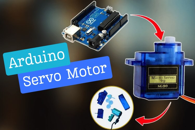
In the world of electronics and robotics, servo motors play a crucial role in controlling mechanical movements precisely. In this blog post, we'll delve into the basics of interfacing a servo motor with an Arduino board. Whether you're a beginner or an experienced enthusiast, this step-by-step guide will help you understand the fundamentals of servo motor control and how to integrate it with an Arduino for your projects. After you have learned the basics you can try other Arduino servo motor projects like this robotic arm using servo motor.
You can also find other such Arduino tutorials and projects on our website.
The components which we will require for this project are
- Arduino Uno
- USB cable
- Servo Motor SG90
- Potentiometer 10k ohm
- Jumper wires
What is a Servo motor?
A servo motor is a type of motor used in various applications to precisely control the position, speed, and angular rotation of mechanical systems. It's designed to provide accurate control of its output shaft, allowing for precise angular position control.
Servo motors typically consist of a small DC motor, a gear train, a control circuit, and a feedback system. The feedback system, often a potentiometer or an encoder, continuously sends information about the motor's current position back to the control circuit. This feedback allows the control circuit to adjust the motor's movement and ensure it reaches and maintains the desired position.
Types of Servo Motors
Servo Motors are divided into two main types
- AC Servo Motor
- DC Servo Motor
AC Servo motors use an AC power source, these motors use encoders for feedback. They are known for their high-speed and high-torque capabilities, making them suitable for industrial machinery and CNC equipment.
DC Servo motors use a DC power source and are often equipped with encoders for feedback. They offer precise control and are commonly used in robotics and small-scale automation.
In this tutorial, we are going to use a DC Servo Motor. If you want to learn more about different types of DC motors in general, You can do that and come back here again.
DC Servo Motors are classified into two types
- Standard rotation Servo which moves from 0 to 180 degrees
- Continuous rotation Servo which moves 360 degrees
We will be using a “Tower pro-Micro Servo sg90 motor” which is a type of DC standard rotation servo motor.
What is Tower Pro SG90 Servo Motor?
The Tower Pro SG90 is a popular and widely used micro servo motor known for its compact size, lightweight design, and affordability. It's commonly utilized in various hobbyist projects, robotics, remote-controlled vehicles, and small-scale applications that require precise control of angular motion.
Specifications of Tower Pro SG90 Servo Motor
Here are the specifications of a standard SG90 Servo we should know before getting/using a servo motor for your project:
| Operating Voltage | 4.8 V - 6 V |
| Stall Torque | 1.6 kg-cm |
| Stall Current | 650 mA |
| Weight | 9g |
| Operating temperature | -30 to +60 degree celsius |
- Operating Voltage: This servo motor operates within a voltage range of 4.8V to 6V. Ensure the power supply falls within this range to prevent damage or inefficient operation.
- Stall Torque: This indicates the maximum torque output of the motor when it's unable to rotate further. It's the force the motor can exert at a given voltage, crucial for applications that require the motor to overcome resistance or hold positions against external forces.
- Stall Current: Stall current refers to the amount of current drawn by a motor when it's operating at stall or maximum load condition, and the shaft is prevented from rotating. It signifies the maximum current which the motor can draw.
- Weight: The weight of the servo motor is essential in applications where size and weight constraints are critical, such as in drones, small robotic arms, or RC vehicles.
- Operating Temperature:Operating temperature refers to the range of temperatures within which a device or component can safely and effectively operate without risking damage or performance degradation.
SG90 Servo Motor Pinout
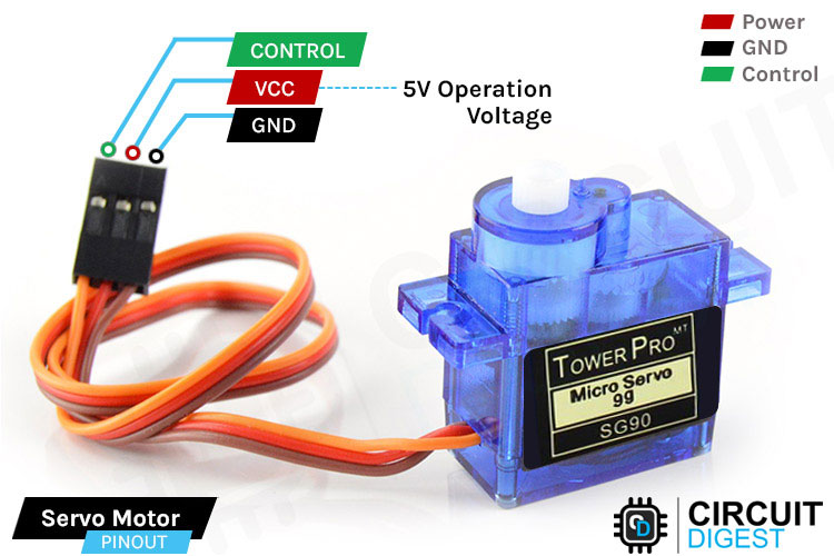
- GND Ground (Brown Wire) – This is the ground pin.
- VCC +5V (Red Wire) – Voltage is supplied to the servo motor through this Pin.
- Control (Orange Wire) – Through this wire, Position control signals are received via PWM.
Servo Motor Working
A servo motor receives PWM (Pulse Width Modulation) signals to determine its angle of rotation. The PWM signal is a square wave with a variable duty cycle, where the width or duration of the high signal (the "on" time) corresponds to a specific angle. This signal is usually generated by a microcontroller, such as an Arduino.
When the PWM signal is fed to the servo motor's control input (usually the orange or yellow wire), the motor's control circuit interprets it as a command to move to a particular angle. The control circuit measures the duration of the high part of the PWM signal, which corresponds to the desired angle. This duration is typically in the range of 1 to 2 milliseconds.
The control circuit then compares this measured duration with the center position (typically 1.5 milliseconds) and adjusts the motor's shaft to move towards the desired angle. If the duration of the high part of the PWM signal is shorter than the center position, the motor turns in one direction; if it's longer, the motor turns in the opposite direction.
The servo motor continuously adjusts its position to match the incoming PWM signal. As the duty cycle of the PWM changes, the motor's shaft rotates accordingly. This closed-loop control mechanism ensures that the motor accurately follows the input signal, allowing for precise and repeatable angular positioning. In essence, the servo motor's responsiveness to PWM signals enables it to execute controlled movements in various applications, from opening and closing doors to steering remote-controlled vehicles.
In addition to using the microcontroller itself, The Servo Motor can be controlled in various other ways.
Servo Shield: A servo shield is used primarily to simplify and streamline the process of controlling multiple servo motors, particularly when working with microcontroller platforms like Arduino.
Here’s how a Servo Shield looks like
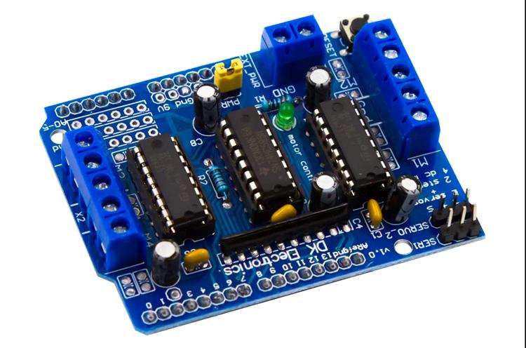
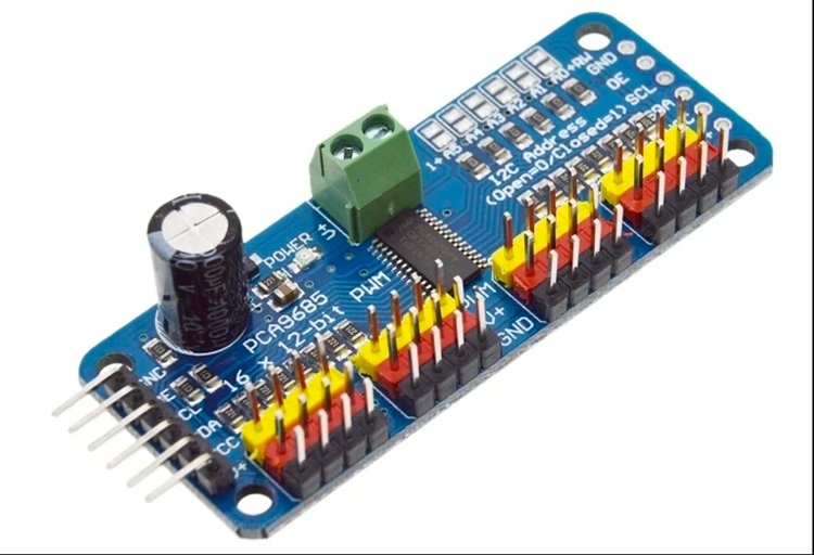
Servomotor driver: The Servo drivers or Arduino Servo controller boards are commonly used to control multiple servo motors in various projects, especially in robotics, automation, and lighting systems.The PCA9685 is a popular 16-channel, 12-bit PWM (Pulse Width Modulation) servo driver. We will also learn a proper implementation of controlling multiple servo using PCA9685 later in this blog.
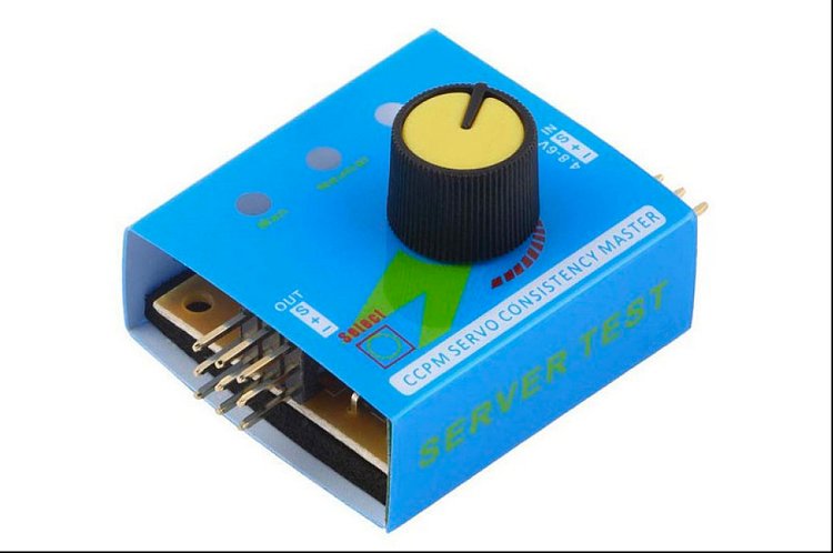
Servo tester: A servo tester is a simple device used to manually test, calibrate, and control servo motors without the need for a microcontroller or complex programming. It's a standalone tool that allows users to directly interface a servo motor with.
Commonly asked questions about Servo Motors
How does a servo motor differ from a regular DC motor?
Unlike a regular DC motor, a servo motor features a closed-loop control system with feedback mechanisms like potentiometers or encoders. This enables precise position control and makes it stop at a specific angle, whereas a regular DC motor doesn't inherently have this level of precision.
Why is my servo jittering or not moving smoothly?
Jittering or erratic movement might be due to power issues, noise in the signal, or mechanical restrictions. Ensure a stable power supply, use proper wiring, and ensure the servo isn't mechanically constrained.
Can I modify a servo motor for continuous rotation?
Yes, some servo models can be modified for continuous rotation by disconnecting the internal feedback mechanism and adjusting the control circuitry. This essentially turns the servo into a geared DC motor with position control disabled.
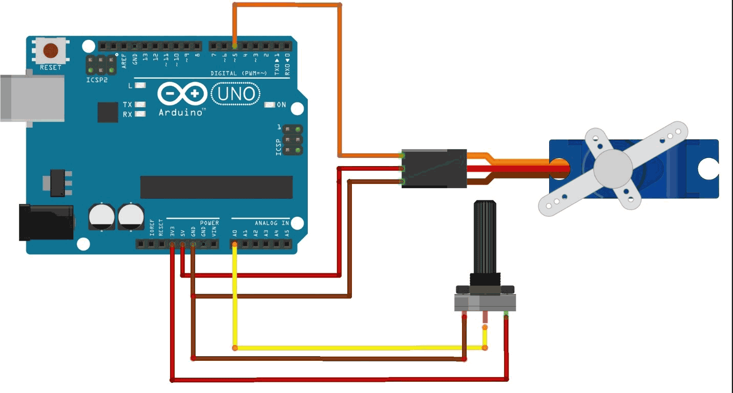
Circuit Diagram of Interfacing Arduino with Servo Motors and Potentiometer
The below circuit diagram shows how a arduino servo motor control can be done using a potentiometer.
- Connect the red wire (VCC) of the servo motor to the 5V pin on the Arduino.
- Connect the brown or black wire (GND) of the servo motor to the GND pin on the Arduino.
- Connect the orange or yellow wire (Signal) of the servo motor to a digital PWM pin on the Arduino.
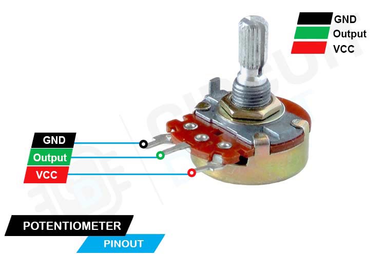
- Connect the positive end of potentiometer to 3.3V pin of Arduino
- Connect the GND end to the GND pin of Arduino
- Connect the signal pin to A0 pin(or any analog input pin)
Here’s a pinout of the potentiometer for reference
Servo Motor Arduino Code
The Arduino Servo Library is a software library that simplifies the control of servo motors using Arduino boards. It provides an easy-to-use interface for managing servo motors' movement and position without the need for intricate programming or handling complex timing functions manually.
To include the Servo Library in your code, you add “#include <Servo.h>” to your code.
There are two important example codes which are used for testing the Servo Motor.
Arduino Servo Sweep Code
This test code rotates the servo from 0 degree to 180 degree and then rotates back from 180 to 0 degree without the need of any input from the user side.
#include <Servo.h>
This line includes the Servo library, which provides functions and features for controlling servo motors in an Arduino sketch.
Servo myservo;
Here, a servo object named myservo is created using the Servo library. This object will be used to control a servo motor connected to the Arduino. The comment indicates that on most Arduino boards, you can create up to twelve servo objects.
int pos = 0;
An integer variable pos is declared and initialized to store the position of the servo motor.
void setup() { myservo.attach(9);
Within the setup() function, myservo.attach(9); is used to attach the servo object myservo to pin 9 of the Arduino. This line informs the Arduino that the servo is connected to pin 9 and that pin will be used to send control signals to the servo.
void loop() { for (pos = 0; pos <= 180; pos += 1) {
myservo.write(pos);
delay(15);
}
The loop() function contains a for loop that increments the pos variable from 0 to 180 degrees in steps of 1 degree using pos += 1. Inside the loop:
myservo.write(pos);
sends the current position value stored in the pos variable to the servo, commanding it to move to that position.
delay(15); pauses the program execution for 15 milliseconds to allow the servo time to reach the specified position.
for (pos = 180; pos >= 0; pos -= 1) {
myservo.write(pos);
delay(15);
}
Following the completion of the first loop, another for loop is used to decrement the pos variable from 180 to 0 degrees in steps of 1 degree using pos -= 1. Inside this loop, the servo is commanded to move to the position specified by the pos variable, and another delay of 15 milliseconds is added between movements.
Here’s how the servo motor tinkercad simulation will look like.
Servo Knob Code
The Arduino knob code is used to control Arduino servo with potentiometer. The code initializes a servo motor on pin 5, reads the analog value from a potentiometer on A0, maps that value to an angle between 0 and 180 degrees, and continuously updates the servo's position based on the potentiometer's value. The small delay aids in smooth movement of the servo motor. Here's the line by line code explantion.you can also find the complete code in the absolute bottom of the blog.
#include <Servo.h>
This line includes the necessary library "Servo.h," which provides functions to control servo motors using the Arduino.
Servo servoMotor;
Here, you're declaring an object named servoMotor of the Servo class. This object will be used to control the servo motor connected to your Arduino.
void setup() {
servoMotor.attach(5);
}
The setup() function is a special function that is executed only once when the Arduino board is powered on or reset. Inside the setup() function, you're using the attach() method of the servoMotor object to connect the servo motor to digital pin 5 on the Arduino. This establishes the communication between the servo motor and the Arduino.
The loop() function is another special function that contains the main code to be executed repeatedly.
int potValue = analogRead(A0);
Inside the loop() function, you're using the analogRead() function to read the analog value from analog pin A0. This value is then stored in the variable potValue.
int servoAngle = map(potValue, 0, 1023, 0, 180);
Here, you're using the map() function to convert the analog potValue (ranging from 0 to 1023) to a desired servo angle range (0 to 180 degrees). This new value is stored in the variable servoAngle.
servoMotor.write(servoAngle);
delay(15);
}
The write() method of the servoMotor object is used to set the servo motor's angle to the calculated servoAngle. A small delay of 15 milliseconds is added using the delay() function. This short delay helps ensure smoother servo motor movement and reduces jitter.
Here’s the servomotor tinkercad simulation which shows how you can control arduino servo with potentiometer
Apart from controlling servo motors with potentiometer, it is also common to control them using push buttons. Previously we have also covered how to control servo motor using push buttons you can check out the link to learn more.
Demonstration of the Project
Here’s how the project output looks like, you can see that in our servo Arduino setup the servo motors is being controlled using the potentiometer.
Controlling multiple Servo Motor using Arduino and PCA9685
The arduino uno has 6 pwm pins only, so you can control upto 6 servo motors using arduino, for more than 6 servo motor control you need to be familiar with a servo motor driver like PCA9686
Controlling multiple servo motors using an Arduino and PCA9685 involves using the PCA9685 module as a servo driver, allowing you to control multiple servos simultaneously through the I2C communication protocol. Here’s a circuit diagram that shows the servo Arduino connection for 4 servo motors.
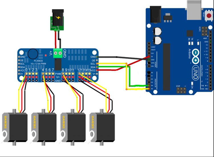
You can use the adafruit PWM Library for this. Just download this library then go to Sketch> Include> Add .Zip library and then guide it to the library download location.
When that is completed, go to file>examples> Adafruit PWM Servo Driver Library > gpiotest and upload the code.
Projects using Arduino
Learn how to create a cost-effective Battery Internal Resistance Meter using an Atmel ATtiny85 microcontroller and Arduino platform. Learn step-by-step instructions, schematic diagrams, and coding techniques to accurately measure battery health through internal resistance. Make your electronics projects better with this insightful tool for better battery management and performance optimization.
Arduino Meets TM1637: Display Module Interfacing Simplified! Learn how to easily connect and program the TM1637 4 Digit Seven Segment Display Module with your Arduino. This concise guide covers wiring, coding, and potential applications, making numeric data visualization a breeze for your projects.
Illuminating Projects: Connect TSL25911 Ambient Light Sensor to Arduino! Unveil the magic of light sensing by seamlessly integrating TSL25911 with Arduino. Our guide walks you through wiring, coding, and creative applications, allowing your projects to perceive and respond to light levels effortlessly.
//Simple Arduino Servo Code
//by CircuitDigest
#include <Servo.h>
Servo servoMotor;
void setup() {
servoMotor.attach(5);
}
void loop() {
int potValue = analogRead(A0);
int servoAngle = map(potValue, 0, 1023, 0, 180);
servoMotor.write(servoAngle);
delay(15); // Small delay for smooth movement
}

