In this digital age, we come across LCDs all around us from simple calculators to smartphones, computers and television sets, etc. The LCDs use liquid crystals to produce images or texts and are divided into different categories based on different criteria like type of manufacturing, monochrome or colour, and weather Graphical or character LCD. In this tutorial, we will be talking about the 16X2 character LCD Modules.
The 16x2 LCDs are very popular among the DIY community. Not only that, but you can also find them in many laboratory and industrial equipment. It can display up to 32 characters at a time. Each character segment is made up of 40 pixels that are arranged in a 5x8 matrix. We can create alphanumeric characters and custom characters by activating the corresponding pixels. Here is a vector representation of a 16x2 LCD, in which you can see those individual pixels.
![]()
As the name indicates, these character segments are arranged in 2 lines with 16 characters on each line. Even though there are LCDs with different controllers are available, The most widely used ones are based on the famous HD44780 parallel interface LCD controller from Hitachi.
16x2 LCD Module Pinout
The 16x2 has a 16-pin connector. The module can be used either in 4-bit mode or in 8-bit mode. In 4-bit mode, 4 of the data pins are not used and in 8-bit mode, all the pins are used. And the connections are as follows:
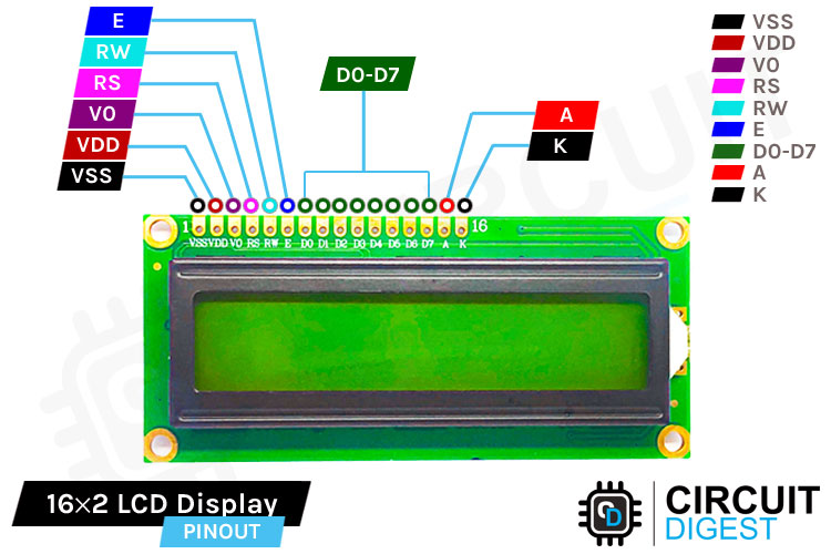
And here are the pins and corresponding functions.
Ground Ground (0V)
VccSupply voltage; 5V (4.7V – 5.3V)
Vo / VEE Contrast adjustment; the best way is to use a variable resistor such as a potentiometer. The output of the potentiometer is connected to this pin. Rotate the potentiometer knob forward and backwards to adjust the LCD contrast.
RS Selects command register when low, and data register when high
Read/write Low to write to the register; High to read from the register
EnableSends data to data pins when a high to low pulse is given; Extra voltage push is required to execute the instruction and EN (enable) signal is used for this purpose. Usually, we set en=0, when we want to execute the instruction, we make it high en=1 for some milliseconds. After this we again make it ground that is, en=0.
DB0 – DB7 8-bit data pins
Led+LED Backlight VCC (5V)
Led-LED Backlight Ground (0V)
16x2 LCD Module – Parts
The 16x2 LCD modules are popular among the DIY community since they are cheap, easy to use and most importantly enable us to provide information very efficiently. With just 6 pins, we can display a lot of data on the display.
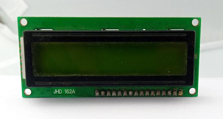
The module has 16 pins. Out of these 16 pins, two pins are for power, two pins are for backlight, and the remaining twelve pins are for controlling the LCD.
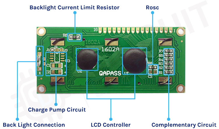
If you look at the backside of the module you can simply see that there are not many components. The main components are the two controller chips that are under the encapsulation. There is an onboard current limiting resistor for the backlight. This may vary from different modules from different manufacturers. The only remaining components are a few complimentary resistors for the LCD controller.
In the module PCB, you may have noticed some unpopulated footprints. These footprints are meant for charge pump circuits based on switched capacitor voltage converters like ICL7660 or MAX660. You can modify your LCD to work with 3.3V by populating this IC and two 10uF capacitors to C1 and C2 footprint, removing Jumper J1 and adding jumper J3. This modification will generate a negative contrast voltage of around 2.5V. This will enable us to use the LCD even with a VCC voltage of 3.3V.
Another issue to be concerned about is the oscillator frequency, i.e. when the supply voltage is reduced, the built-in clock frequency will also get reduced. The Rosc should be changed to a suitable value if any timing issues or command execution issues occur. The typical value of the Rosc for 5V VCC is 91KOhms.
Commonly Asked Questions about 16x2 LCD
How do I know if my 16x2 LCD is working?
To test whether a 16x2 LCD works or not, connect the VDD, GND and backlight pins to 5v and GND. Connect the centre terminal of a 10K variable resistor to the VEE pin. Connect the other two terminals to VCC and GND. Simply rotate the variable resistor you will see that the contrast will be adjusted and small blocks are visible. If these rectangles are visible, and you were able to adjust the contrast, then the LCD is working
How many pins are there in LCD?
There are 16 pins on the display module. Two of them are for power (VCC, GND), one for adjusting the contrast (VEE), three are control lines (RS, EN, R/W), eight pins are data lines(D0-D7) and the last two pins are for the backlight (A, K).
How does a 16x2 LCD screen work?
The 16x2 LCD has 32 character areas, which are made up of a 5x8 matrix of pixels. By turning on or off these pixels we can create different characters. We can display up to 32 characters in two rows.
Can we display custom characters on 16x2 LCD?
Yes, we can. We can store up to eight custom characters in the CGRAM (64 bytes in size) area. We can create load the matrix data for these characters and can recall when they need to be displayed.
How to Control 16x2 LCD Module
Controlling the LCD module is pretty simple. Let’s walk through those steps. To adjust the contrast of the LCD, the Vo/ VEE pin is connected to a variable resistor. By adjusting the variable resistor, we can change the LCD contrast.
The RS or registry select pin helps the LCD controller to know whether the incoming signal is a control signal or a data signal. When this pin is high, the controller will treat the signal as a command instruction and if it’s low, it will be treated as data. The R/W or Read/Write pin is used either to write data to the LCD or to read data from the LCD. When it’s low, the LCD module will be in write mode and when it’s high, the module will be in reading mode.
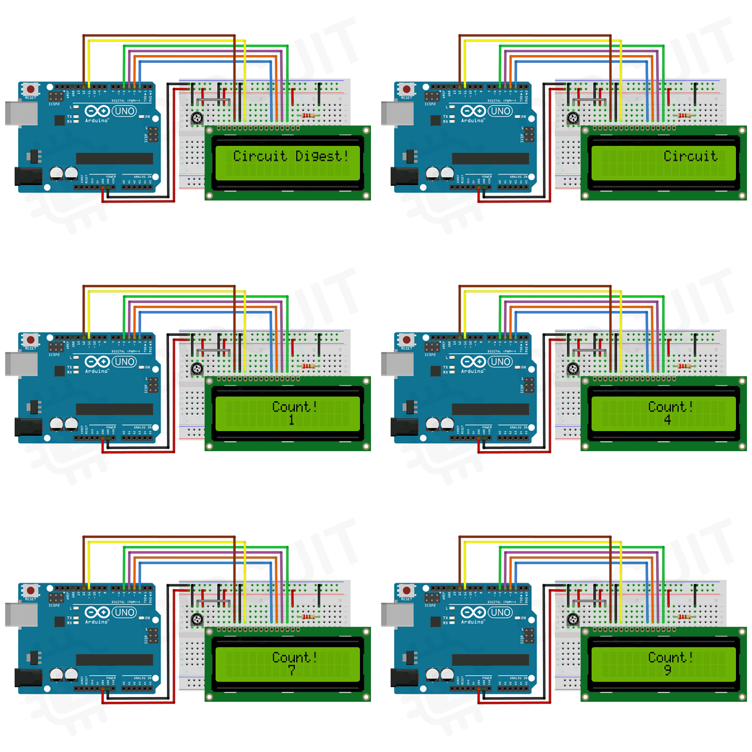
The Enable pin is used to control the LCD data execution. By default, this pin is pulled low. To execute a command or data which is provided to the LCD data line, we will just pull the Enable pin to high for a few milliseconds.
How to Test the 16X2 LCD Module
To test the LCD module, connect the VDD, GND, and backlight pins to 5v and GND. Connect the center terminal of a 10K variable resistor to the VEE pin. Connect the other two terminals to VCC and GND as per the below connection diagram-
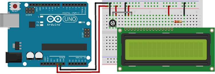
Simply rotate the variable resistor you will see that the contrast will be adjusted and small blocks are visible. If these rectangles are visible, and you were able to adjust the contrast, then the LCD is working.
Interfacing 16x2 LCD with Arduino
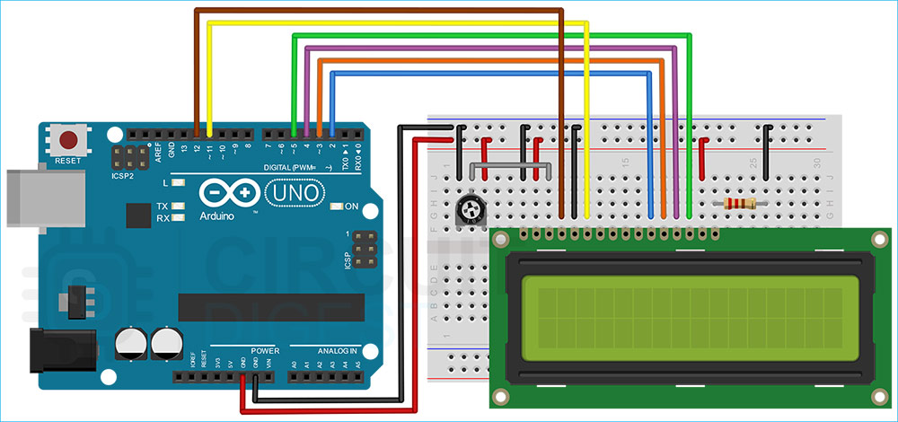
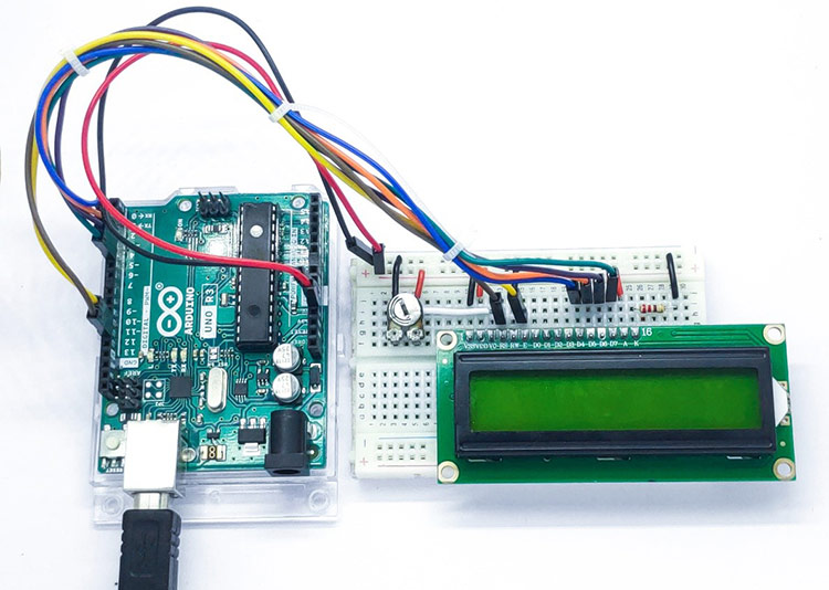
Let’s see how to connect the LCD module to Arduino. For that first, connect the VSS to the GND and VDD to the 5V. To use the LCD backlight, connect the backlight Anode to the 5V and connect the backlight cathode to the GND through a 220Ωresistor. Since we are not using the read function connect the LCD R/W pin to the GND too. To adjust the contrast, connect the centre pin of a 10KΩ trimmer resistor to the VEE pin and connect the side pins to the VCC and GND. Now connect the registry select pin to D12 and Enable pin to D11.
Now let’s connect the data pins. The LCD module can work in two modes, 8-bit and 4-bit. 8-bit mode is faster but it will need 8 pins for data transfer. In 4-bit mode, we only need four pins for data. But it is slower since the data is sent one nibble at a time. 4-bit mode is often used to save I/O pins, while the 8-bit mode is used when speed is necessary. For this tutorial, we will be using the 4-bit mode. For that connect the D4, D5, D6 and D7 pins from the LCD to the D5, D4, D3 and D2 pins of the Arduino.
Here is the actual circuit. It is built as per the connection diagram provided. All the connections are made using standard male to male jumper wires.
Arduino Code to Interface 16x2 LCD
The following Arduino 16x2 LCD code will print Hello, World! on the first line of the display and the time the Arduino was running in seconds on the second line.
// include the library code:
#include <LiquidCrystal.h>
// initialize the library by associating any needed LCD interface pin
// with the arduino pin number it is connected to
const int rs = 12, en = 11, d4 = 2, d5 = 3, d6 = 4, d7 = 5;
LiquidCrystal lcd(rs, en, d4, d5, d6, d7);
void setup() {
  // set up the LCD's number of columns and rows:
  lcd.begin(16, 2);
  // Print a message to the LCD.
  lcd.print(" Circuit Digest!");
  delay(2000);
  for (int positionCounter = 0; positionCounter < 16; positionCounter++) {
    // scroll one position right:
    lcd.scrollDisplayRight();
    // wait a bit:
    delay(150);
  }
  lcd.clear();
  lcd.setCursor(6, 0);
  lcd.print("Count!");
  // print the number of seconds since reset:
}
void loop() {
  for (int i = 0; i < 10; i ++)
  {
    lcd.setCursor(8, 1);
    // print the number of seconds since reset:
    lcd.print(i);
    delay(1000);
  }
}
Now let’s discuss the code. As usual, the sketch starts by including the necessary libraries. For this tutorial, we will be including the LiquidCrystal library from Arduino. This library is compatible with LCDs based on the Hitachi HD44780, or any compatible chipset. You can find more details about this library on the Arduino website.
// include the library code:
#include <LiquidCrystal.h>
Let’s create an object to use with the LiquidCrystal library. The following line of code will create an object called lcd. We will be using this object in the entire code to access the library functions. The object is initialized with the pin numbers.
// initialize the library by associating any needed LCD interface pin
// with the Arduino pin number it is connected to
const int rs = 12, en = 11, d4 = 2, d5 = 3, d6 = 4, d7 = 5;
LiquidCrystal lcd(rs, en, d4, d5, d6, d7);
Now let’s look at the setup() function. The lcd.begin function is used to initialize the LCD module. This function will send all the initialization commands. The parameters used while calling this function are the number of columns and the number of rows. And the next function is lcd.print. with this function, we have printed the word Circuit Digest! to the LCD. Since the LCD cursor is set to home position within the lcd.begin, we don’t need to set any cursor position. This text will stay there for two seconds. After that, the text will scroll from left to right until the entire text is out of the display. To scroll the display to the right, we have used the function lcd.scrollDisplayRight. After that, to clear display, we used lcd.clear, this will clear any characters on the display.
Next, the cursor is set to the sixth position on the first row, and the counting number is printed to the LCD.
void setup() {
  // set up the LCD's number of columns and rows:
  lcd.begin(16, 2);
  // Print a message to the LCD.
  lcd.print(" Circuit Digest!");
  delay(2000);
  for (int positionCounter = 0; positionCounter < 16; positionCounter++)

{
    // scroll one position right:
    lcd.scrollDisplayRight();
    // wait a bit:
    delay(150);
     }
  lcd.clear();
  lcd.setCursor(6, 0);
  lcd.print("Count!");
  // print the number of seconds since reset:
}
Now let’s look at the loop function. The for loop will count from 0 to 9, and when it reaches 9, it will reset the count and repeat the process all over again. lcd.setCursor is used to set the cursor position. lcd.setCursor(8, 1) will set the LCD cursor to the eighth position in the second row. In the LCD, the first row is addressed as 0 and the second row is addressed as 1. And the lcd.print(i) will print the count value stored in the variable i to the display.
void loop() {
  for (int i = 0; i < 10; i ++)
  {
    lcd.setCursor(8, 1);
    // print the number of seconds since reset:
    lcd.print(i);
    delay(1000);
  }
}
16x2 LCD Module Problems and Troubleshooting Steps
- Wrong characters are displayed: This problem occurs usually when the LCD is not getting the correct data. Make sure you are sending the correct ASCII value. If you are sending the correct ASCII characters, but still showing the wrong one on the LCD, check your connections for loose contact or short circuits.
- Display shows Black boxes or does not show anything: First thing to do in these situations is to adjust the contrast voltage by rotating the variable resistor. This will correct the contrast value and will give you a visible readout.
- Contrast is Ok, but still no display: Make sure to provide a sufficient time delay in between sending each character. Because if you don’t give enough time to process the data the display will malfunction.
- Contrast and delay are ok, but still no display: Make sure you are powering the LCD from a 5V source. By default, these displays won’t work with a supply voltage below 5V. So if you are using the display with a 3.3V microcontroller make sure to power the display from 5V and use level shifters in between the display and the microcontroller.
Projects Using 16x2 LCD Display Module
There are some interesting projects done with the 16x2 LCD. If you want to know more about those topics, links are given below.
In this tutorial, we will see how to interface a 16x2 LCD with ARM7-LPC2148 microcontroller and display a simple welcome message.
In this tutorial, we will learn how to interface a LCD with STM8 Microcontroller. We have provided Circuit Diagram, Code, and Step-by-step guide.
In this project we will provide the input voice using Google Voice Keyboard via a Android App (BlueTerm) and print the text on 16x2 LCD using Raspberry Pi.
In this tutorial we are interfacing a Liquid Crystal Display (LCD) module with the Raspberry Pi Pico using Micropython to display strings, and characters on the LCD.
We used some Python scripts to find the local IP address of your Raspberry Pi on the network and display it on the 16x2 LCD Screen. We also added the script in the Crontab so that it can be run on every 10 minutes and we will have the updated IP address every time.
Supporting Files
// include the library code:
#include <LiquidCrystal.h>
// initialize the library by associating any needed LCD interface pin
// with the arduino pin number it is connected to
const int rs = 12, en = 11, d4 = 2, d5 = 3, d6 = 4, d7 = 5;
LiquidCrystal lcd(rs, en, d4, d5, d6, d7);
void setup() {
// set up the LCD's number of columns and rows:
lcd.begin(16, 2);
// Print a message to the LCD.
lcd.print(" Circuit Digest!");
delay(2000);
for (int positionCounter = 0; positionCounter < 16; positionCounter++) {
// scroll one position right:
lcd.scrollDisplayRight();
// wait a bit:
delay(150);
}
lcd.clear();
lcd.setCursor(6, 0);
lcd.print("Count!");
// print the number of seconds since reset:
}
void loop() {
for (int i = 0; i < 10; i ++)
{
lcd.setCursor(8, 1);
// print the number of seconds since reset:
lcd.print(i);
delay(1000);
}
}

