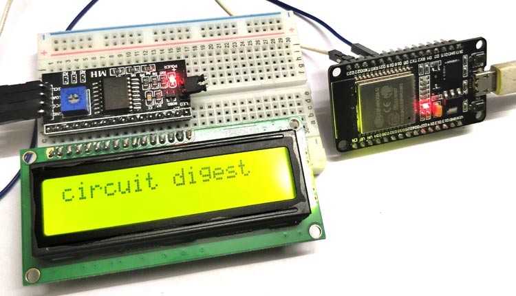
In previous tutorial, OLED is interfaced with ESP32 using SPI communication which uses 5 pins. In this tutorial, we interface 16x2 LCD with ESP32, using only 2 pins, with the help of I2C communication. It reduces number of pins used by ESP32 so that more number of ESP32 pins remain free for interfacing different sensors.
What is I2C Communication Protocol?
The term I2C stands for “Inter Integrated Circuits”. It is normally denoted as IIC or I squared C or even as 2-wire interface protocol (TWI) at some places but it all means the same. I2C is a synchronous communication protocol, means both the devices that are sharing the information must share a common clock signal. It has only two wires, SDA and SCL to share information, out of which SCL is used for the clock signal and SDA is used for sending and receiving data.
You can buy I2C LCD module in which I2C1602 LCD Controller is inbuilt or you can simply buy I2C controller to interface 16x2 LCD with ESP32.
Materials Required
- ESP32
- 16*2 LCD display
- I2C LCD controller
- Wires
- Breadboard
I2C Module
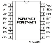
I2C controller has an IC PCF8574 which provides general-purpose remote I/O expansion via the two-wire bidirectional I2C-bus serial clock (SCL) and serial data (SDA). It is very useful IC and can be used in LED signs boards, displays, Key pads, Industrial control, etc. There are 8 I/O pins, 3 pins (A0, A1, A2) for I2C bus address and SDA, SCL pins.
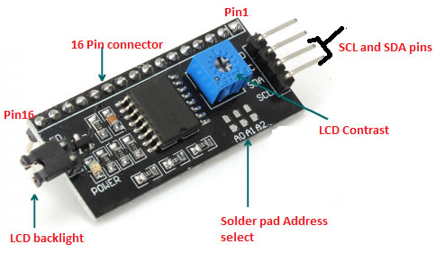
LCD controller board has an inbuilt potentiometer to control contrast of LCD.
Pin diagrams of IC and LCD controller are given below.
Circuit diagram
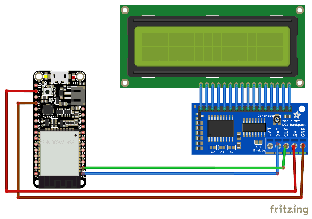
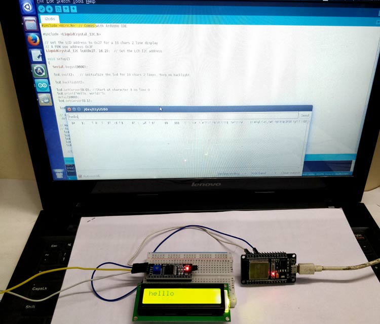
Connections for interfacing LCD with ESP32 is given below
- connect pin 1-16 of I2C module to pin 1-16 of LCD display.
- SDA pin of I2C module -> SDA pin of ESP32 i.e D21
- SCL pin of I2C module -> SCL pin of ESP32 i.e D22
I have connected 3v of ESP32 to 5v of I2C for demonstration only but we need 5V supply for the I2C module to display data properly, because ESP32 can only give 3.3 volts which is low for the I2C module and data won’t be visible clearly. So, it’s better to use external 5V supply.
We need board files for ESP32, so if you are new to ESP32 then first follow Getting Started with ESP32 Tutorial and then jump back here. You can also connect LCD with ESP32 without I2C but it will take more pins of ESP32.
Code for finding I2C Controller Address
Before going into the main code we have to first find the address of I2C module.
I2C controller has inbuilt ADDRESS bit which is used to control I2C bus. The default ADDRESS is 0x27 but in some cases it can be 0x3f. So, to check the address of the I2C controller, connect the circuit as shown above upload the below given code and open serial monitor, You will see the address in hexadecimal.
#include <Wire.h>

void setup() {
Serial.begin (9600);
Serial.println ("Scanning I2C device...

Wire.begin();
for (byte i = 0; i <50; i++)
{
Wire.beginTransmission (i);
if (Wire.endTransmission () == 0)
{
Serial.print ("Address found->");
Serial.print (" (0x");
Serial.print (i, HEX);
Serial.println (")");
Count++;
}
Serial.print ("Found ");
Serial.print (count, DEC);
Serial.println (" device");
}

void loop() {}
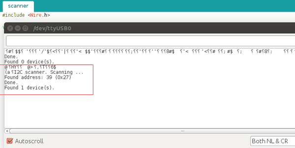
Note we use this Address in our LCD interface code.
In I2C controller, as you can see there are three jumpers/soldering pads labelled as A0, A1 and A2. These are used to change the address of the module. Here's how the address changes from the default value 0x27 or 0x3F, if you connect the address pads together. (1 = Not Connected. 0 = Connected):
|
A0 |
A1 |
A2 |
HEX Address |
|
1 |
1 |
1 |
0x27 |
|
0 |
1 |
1 |
0x26 |
|
1 |
0 |
1 |
0x25 |
|
0 |
0 |
1 |
0x24 |
|
1 |
1 |
0 |
0x23 |
|
0 |
1 |
0 |
0x22 |
|
1 |
0 |
0 |
0x21 |
|
0 |
0 |
0 |
0x20 |
Code for ESP32
First we need a library LiquidCrystal_I2C for I2C LCD module. Ordinary Liquidcrsytal library will not work because we are using I2C here.
Download library from this https://github.com/fdebrabander/Arduino-LiquidCrystal-I2C-library
The code is written in such way that whatever is typed on serial monitor, will be displayed on LCD. Arduino IDE has been used to write and upload our code.
First, we have to include wire library for I2C communication which comes with Arduino IDE.
#include <Wire.h>
Then for I2C LCD, include LiquidCrystal_I2C.h that is downloaded earlier.
#include <LiquidCrystal_I2C.h>
Then set the LCD I2C address to 0x27 or the address you got by running the scanner code given above for a 16 chars 2 line display
LiquidCrystal_I2C lcd(0x27, 16,2);
In setup function, initialize the serial communication and LCD for 16 chars 2 lines and turn on the backlight. If you want to turn off the backlight use lcd.noBacklight() and change setCursor() function according to your preference.
void setup()
{
Serial.begin(9600);
lcd.init();
lcd.backlight();
lcd.setCursor(0,0);
lcd.print("Hello, world!");
delay(1000);
lcd.setCursor(0,1);
lcd.print("circuitdigest.com");
delay(3000);
LCD will first display the instructions to use Serial Monitor and type the characters to display.
Set the Serial Monitor option to "No Line Ending"
lcd.clear();
lcd.setCursor(0,0);
lcd.print("Use Ser. Monitor");
lcd.setCursor(0,1);
lcd.print("Type to display");
}
loop function will continuous check for any incoming serial data from serial port using Serial.available() function. If there is a message, it wait for second and print the message on the LCD using lcd.write() and Serial.read() functions.
void loop()
{
{

// when characters arrive over the serial port...
if (Serial.available()) {

delay(100);               // wait a bit for the entire message to arrive

lcd.clear();                // clear the screen

while (Serial.available() > 0) {                // read all the available characters

lcd.write(Serial.read());             // display each character to the LCD
}
}
}
}
Compete Code is given below, so upload the code and open serial monitor. Then type message and hit enter .Your message will be displayed on LCD.
If you don’t get proper or no response on the LCD then check your I2C controller address or scan it again with the above given code to get the correct address.
#include <Wire.h>
#include <LiquidCrystal_I2C.h>
LiquidCrystal_I2C lcd(0x27, 16,2);
void setup()
{
Serial.begin(9600);
lcd.init();
lcd.backlight();
lcd.setCursor(0,0);
lcd.print("Hello, world!");
delay(1000);
lcd.setCursor(0,1);
lcd.print("circuitdigest.com");
delay(3000);
lcd.clear();
lcd.setCursor(0,0);
lcd.print("Use Ser. Monitor");
lcd.setCursor(0,1);
lcd.print("Type to display");
}
void loop()
{
{
if (Serial.available()) {
delay(100);
lcd.clear();
while (Serial.available() > 0) {
lcd.write(Serial.read();
}
}
}
}

