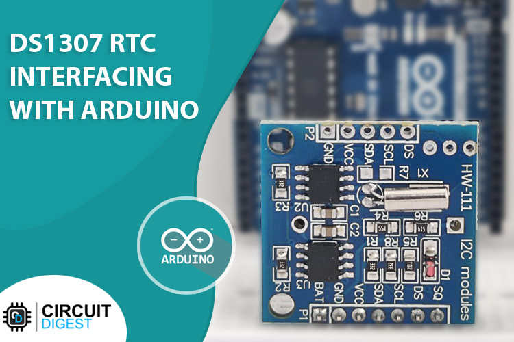
Time is vital in today's society, and when it comes to certain electronics, timing is crucial; just like us, they require a means to keep track of time, and precise time. So, how do electronics accomplish this? A Real-Time Clock, or RTC, is a timekeeping device embedded inside an Integrated Circuit, or IC. The answer is DS1307. Many time-critical applications and devices rely on it, including servers, GPS, and data loggers.
About the DS1307
The DS1307 is a battery-backed clock/calendar with 56 bytes of SRAM. The clock/calendar displays data in seconds, minutes, hours, days, dates, months, and years. Each month's end date is automatically changed, particularly for months with fewer than 31 days.
They come in the form of integrated circuits (ICs) that control time like a clock and date like a calendar. The key advantage of RTC is that it has a battery backup system that keeps the clock/calendar working even if the power goes out. The RTC requires a tiny amount of electricity to stay active. These RTCs may be found in various applications, including embedded devices and computer motherboards.
DS1307 Pinout
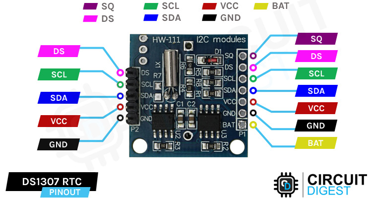
SQThe pin may be programmed to emit one of four square-wave frequencies: 1Hz, 4kHz, 8kHz, or 32kHz.
DS If your module has a DS18B20 temperature sensor fitted immediately next to the battery holder, the pin is designed to output temperature information (labeled as U1).
SCL is the I2C interface's clock input, which is used to synchronize data transfer across the serial interface.
SDA is the I2C serial interface's data input/output.
VCC This pin powers the module. It can range from 3.3 to 5.5 volts.
GND is a ground pin.
BAT is a backup supply input for any standard 3V lithium battery or another energy source that allows the gadget to keep a precise time when the primary power is lost.
DS1307 Module Parts

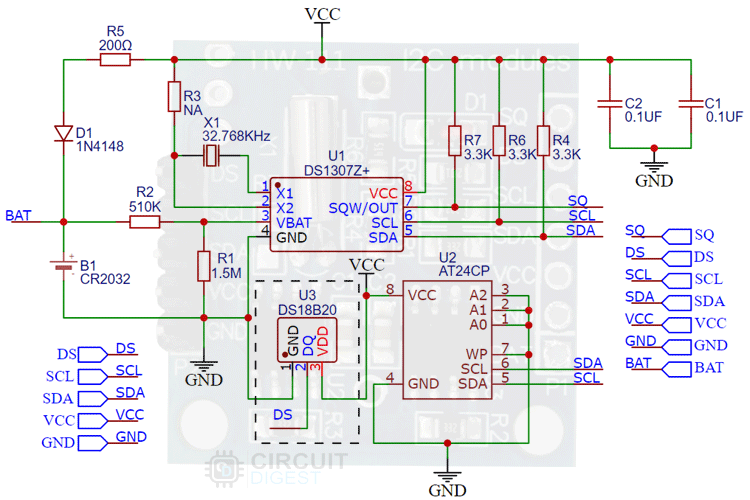
The DS1307 RTC module includes all onboard components necessary for the proper operation of a DS3107 chip. Furthermore, it has a holder for a 20mm 3V lithium coin battery. Any CR2032 battery can be used in this module. Let's go through each of the module's components one by one. The DS1307 keeps track of the seconds, minutes, hours, days, and months. This chip resets its seconds, minutes, hours, and date at the end of every month. Time can be displayed in 12-hour format with AM and PM or in 24-hour format.
32kHz Crystal Oscillator:
The DS1307 chip requires a 32KHz external crystal oscillator to function (time-keeping). As a result, the RTC module has a 32KHz external crystal oscillator. However, there is one issue with this 32KHz crystal oscillator: changes in ambient temperature alter the crystal oscillator's oscillation frequency. The difference in the external crystal oscillation frequency of 32KHz is insignificant. However, in the long term, it is a mistake. It causes a monthly clock drift of 2-3 minutes.
Onboard 24C32 EEPROM:
The DS1307 RTC module also has a 24C32 EEPROM onboard. This EEPROM has a 32-byte capacity and only allows for regional read-write operations. Using an RTC module for Alarm-based projects may leverage this memory to save time. For example, we wish to wake up every day at 8:00 a.m. We may record this time value in EEPROM, and an alarm will sound anytime the time equals the saved value.
These EEPROM chips use the I2C interface to connect with microcontrollers like Arduino. As a result, it uses the same I2C bus as the DS1307. To communicate with EEPROM (o 0x50 Hex) and DS1307 chip on the same I2C bus, different slave addresses are set to them.
Backup Battery:
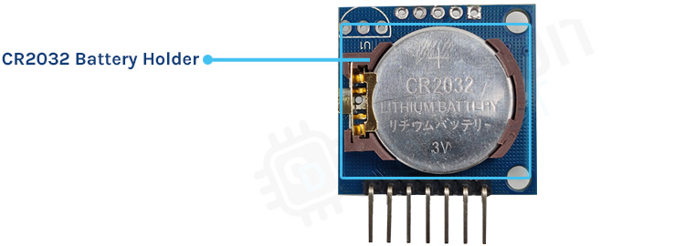
A holder for connecting a CR2032 coil cell may be found on the rear side of an RTC module. This backup battery is intended to preserve precise time even if the primary power supply attached to the DS1307 fails. This chip has a power sensor circuit that detects main power and switches to the backup coil cell when main power is lost.
DS18B20 Sensor:
An external DS18B20 digital temperature sensor can be connected to an empty slot on this module. The three empty pinouts in the bottom right corner serve as a placeholder for the DS18B20 sensor, whose output may be received through the RTC module's DS pin.
DS1307 Sensor Module Schematic
Programming the DS1307 and Setting Time
Connecting the DS1307 module to the Arduino in the setup below is all that is required to set up time in the module.
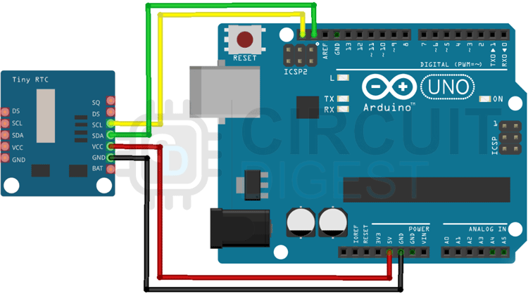
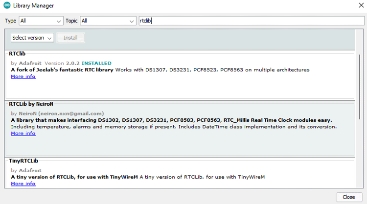
After making the above connections, you need to connect the Arduino Uno to your PC, open Arduino IDE, and install Arduino DS1307 Time Set Library. Open the Arduino IDE and select Library Manager from the menu bar. Now look for RTCLib and get the most recent version, as shown in the figure below.
The code is simple to understand. The time will be set and shown on the serial monitor.
rtc.adjust(DateTime(F(__DATE__),F(__TIME__)));
In this line, the rtc object adjusts the time according to the time on your machine. It will modify the time on your computer.
rtc.adjust(DateTime(2014, 1, 21, 3, 0, 0));
You may manually set the time on this line by giving the following date-time values to the function: year, month, day, hour, minute, and second. In the code below, we'll set the system's time. As a result, this line has been commented out.
#include <RTClib.h>
#include <Wire.h>
RTC_DS3231 rtc;
char t[32];
void setup()
{
  Serial.begin(9600);
  Wire.begin();
  rtc.begin();
  rtc.adjust(DateTime(F(__DATE__),F(__TIME__)));
  //rtc.adjust(DateTime(2019, 1, 21, 5, 0, 0));
}
void loop()
{
  DateTime now = rtc.now();
  sprintf(t, "%02d:%02d:%02d %02d/%02d/%02d", now.hour(), now.minute(), now.second(), now.day(), now.month(), now.year());
  Serial.print(F("Date/Time: "));
  Serial.println(t);
  delay(1000);
}
Now we know how to set time in the module, let's use it with an LCD to make a simple clock
Material Required
- Arduino Uno
- DS1307 Module
- LCD Display
- I2C LCD Driver Module
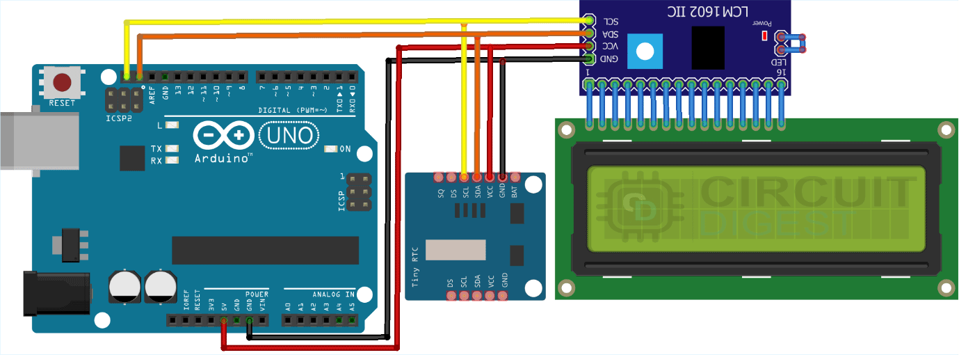
After gathering the above material, make the connections indicated in the circuit diagram below.
Connect the DS1307 RTC's SDA and SCL pins to Arduino's SDA and SCL pins. To show the date and time, a 16x2 LCD is attached.
Code to display time on LCD
Wire.h is used to connect with the module via I2C, LiquidCrystal_I2C.h is used to show time on the LCD display, and RTClib.h is used to set and format the time on the display.
#include <Wire.h>
#include <LiquidCrystal_I2C.h>
#include <RTClib.h>
This line sets the address for the 16x2 LCD display to communicate over the I2C protocol.
LiquidCrystal_I2C lcd(0x27,16,2);
The code will report DS1307 RTC Module is not Present on the serial monitor if the project is started with a broken connection.
if (! rtc.begin())
  {
    Serial.println("DS1307 RTC Module is not Present");
    while (1);
  }
If the RTC loses power and the time in the module becomes incorrect, the code will automatically adjust the time in the module using the computer's clock. So make sure the clock on your computer is set to the correct time when setting the time.
if (rtc.lostPower())
  {
    Serial.println("RTC power failure, resetting the time!");
    rtc.adjust(DateTime(F(__DATE__), F(__TIME__)));
  }
This code block resets the LCD cursor to 0 and outputs the date in the Date/Month/Year format.
void displayTime()
 {
  lcd.setCursor(0,0);
  lcd.print("Time:");
  lcd.print(now.hour());
  lcd.print(':');
  lcd.print(now.minute());
  lcd.print(':');
  lcd.print(now.second());
  lcd.print("    ");
 }
The cursor is set to 1 in this portion of the code, and the time is printed in the format Hour: Minute: Second.
void displayDate()
 {
  lcd.setCursor(0,1);
  lcd.print("Date:");
  lcd.print(now.day());
  lcd.print('/');
  lcd.print(now.month());
  lcd.print('/');
  lcd.print(now.year());
 }
The date and time will appear on the LCD screen when you have entered the code.
Frequently Asked Questions about DS1307 RTC Module
What is the difference between DS1307 and DS3231?
The only difference between the DS3231 and the DS1307 is that the DS3231 has a temperature compensated crystal built-in, which makes it more precise, but the chip is also considerably bigger. They share the same I2C address, thus libraries designed for the DS1307 should also function for the DS3231.
What is the address of DS1307?
The address byte starts with the 7-bit DS1307 address, which is 1101000, and then the *direction bit (R/W), which is a 0 for a write. The device produces an acknowledge on the SDA line after receiving and decoding the address byte.
What is the frequency of the clock used in RTC?
The 32-kHz clock is used to run the RTC. There are fixed-length seconds and one variable-length second for each hour. There are 3599 seconds of constant length. The 32-kHz clock ticks precisely 32,768 times per second.
Supporting Files
#include <Wire.h>
#include <LiquidCrystal_I2C.h>
#include <RTClib.h>
DateTime now;
RTC_DS3231 rtc;
LiquidCrystal_I2C lcd(0x27,16,2);
void displayDate(void);
void displayTime(void);
void setup ()
{
Serial.begin(9600);
lcd.begin();
lcd.backlight();
if (! rtc.begin())
{
Serial.println("DS1307 RTC Module not Present");
while (1);
}
if (rtc.lostPower())
{
Serial.println("RTC power failure, resetting the time!");
rtc.adjust(DateTime(F(__DATE__), F(__TIME__)));
}
}
void loop ()
{
now = rtc.now();
displayDate();
displayTime();
}
void displayTime()
{
lcd.setCursor(0,0);
lcd.print("Time:");
lcd.print(now.hour());
lcd.print(':');
lcd.print(now.minute());
lcd.print(':');
lcd.print(now.second());
lcd.print(" ");
}
void displayDate()
{
lcd.setCursor(0,1);
lcd.print("Date:");
lcd.print(now.day());
lcd.print('/');
lcd.print(now.month());
lcd.print('/');
lcd.print(now.year());
}


