The damages that can be done by fire are devastating. To prevent causalities or damages, it is necessary to detect the fire, so that warnings can be provided and even automatic fire suppression systems can be activated. There are multiple ways to detect a fire, like detecting temperature change, smoke detection, etc. In all of these, detecting temperature change would be more accurate, since some fires won’t even have detectable smoke. Even the temperature measurement is not too dependable since sometimes it’s too late when the change is detected. To overcome this, we can detect the thermal radiation instead of the temperature variation. The easiest and cheapest way to detect thermal radiation is to use a flame sensor. In this tutorial, we will see how we can interface a flame sensor module with Arduino.
Flame Sensor Module Pinout
The flame sensor module has a total of 4 pins. Two power pins and two signal pins. The pinout of a flame sensor module is as follows:
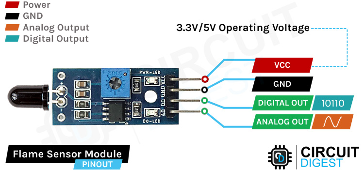
VCC Provides power for the module, Connect to the 5V pin of the Arduino.
GND Ground Connected to Ground pin of the Arduino.
DO Digital Output Pin.
AO Analog Output Pin.
Flame Sensor Module Parts
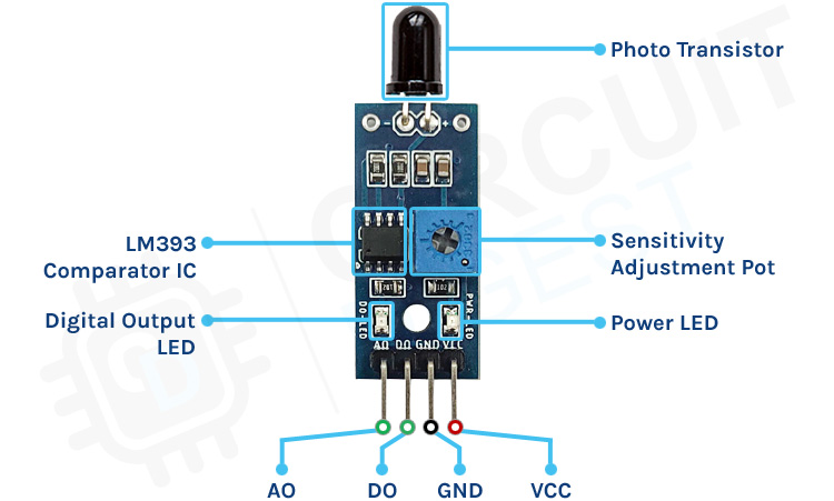
The flame sensor module has only very few components, which include an IR photodiode, an LM393 comparator IC, and some complimentary passive components. The power LED will light up when the module is powered and the D0 LED will turn off, when a flame is detected. The sensitivity can be adjusted with the trimmer resistor onboard.
Commonly Asked Questions about Flame Sensor
How does a flame sensor work?
The flame sensor works based on infrared radiation. The IR photodiode will detect the IR radiation from any hot body. This value is then compared with a set value. Once the radiation reaches the threshold value, the sensor will change its output accordingly.
What does the flame sensor detect?
This type of flame sensor detects Infrared radiation.
Where are flame sensors used?
The flame sensors are used where ever there is a chance for a fire. Especially in industrial areas.
Flame Sensor Module Circuit Diagram
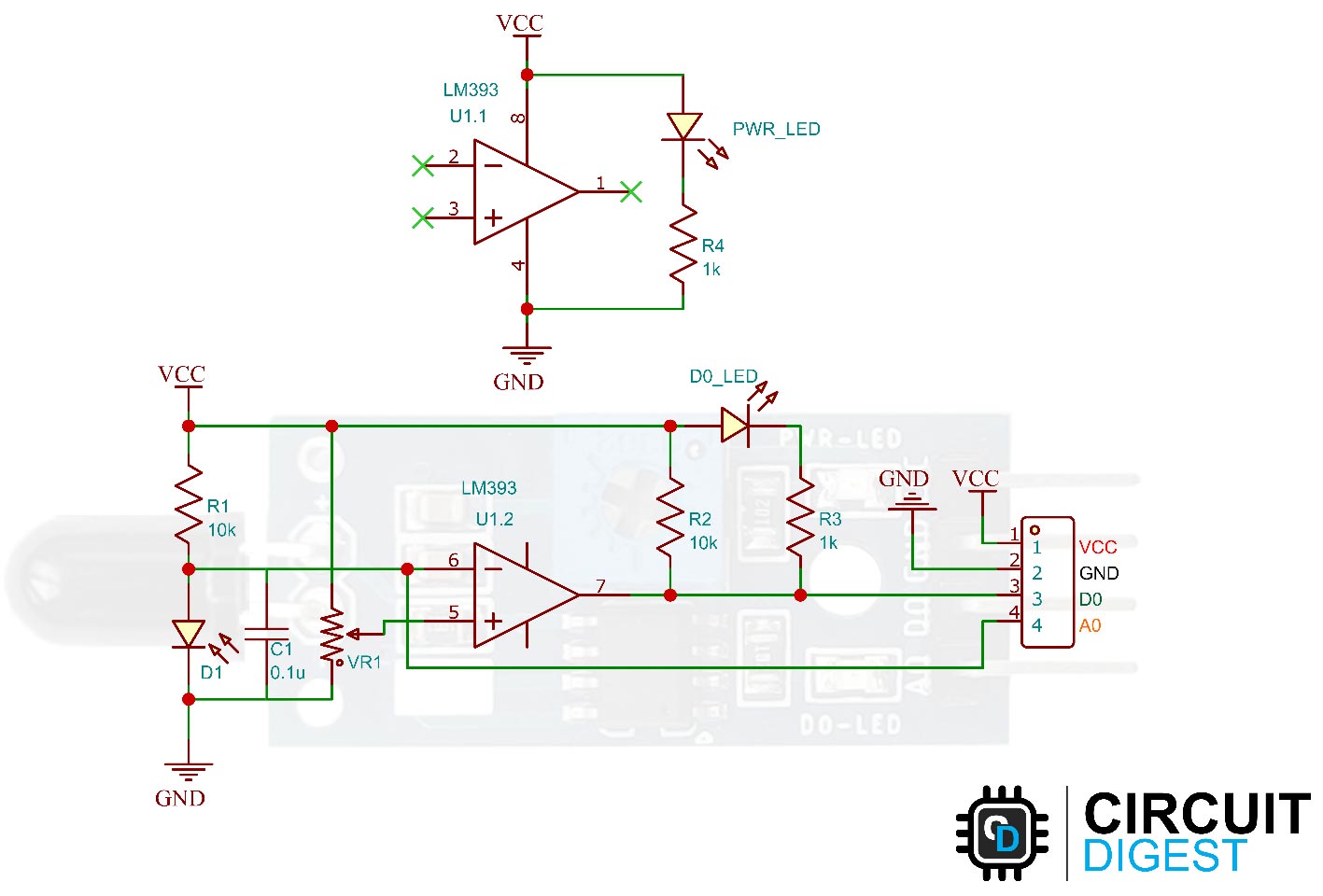
The schematic diagram for the flame sensor module is given below. As mentioned earlier, the board has a very low component count. The main components are the IR photodiode and the comparator circuit.
How does the Flame Sensor Module Works?
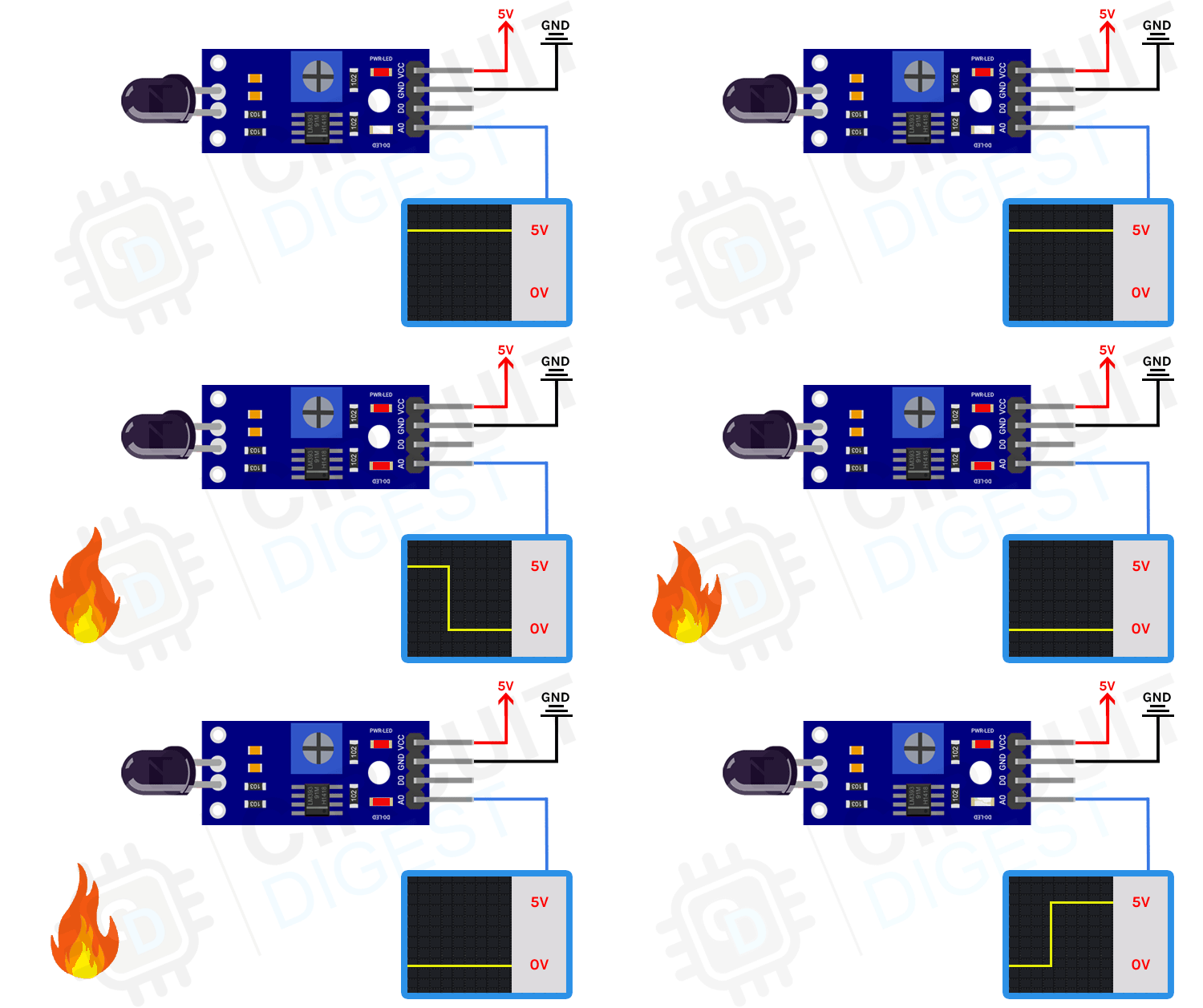
The working of the flame sensor module is simple. The theory behind it is that a hot body will emit infrared radiation. And for a flame or fire, this radiation will be high. We will detect this IR radiation using an infrared photodiode. The conductivity of the photodiode will vary depending on the IR radiation it detects. We use an LM393 to compare this radiation and when a threshold value is reached the digital output is changed.

We can also use the analog output to measure the IR radiation intensity. The analog output is directly taken from the terminal of the photodiode. The onboard D0 LED will show the presence of fire when detected. The sensitivity can be changed by adjusting the variable resistor on board. This can be used to eliminate false triggering.
Arduino Flame Sensor Interfacing Circuit Diagram
Now that we have completely understood how a Flame Sensor works, we can connect all the required wires to Arduino and write the code to get all the data out from the sensor. The following image shows the circuit diagram for interfacing the flame sensor module with Arduino.
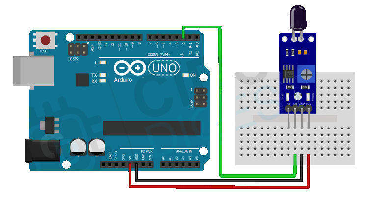
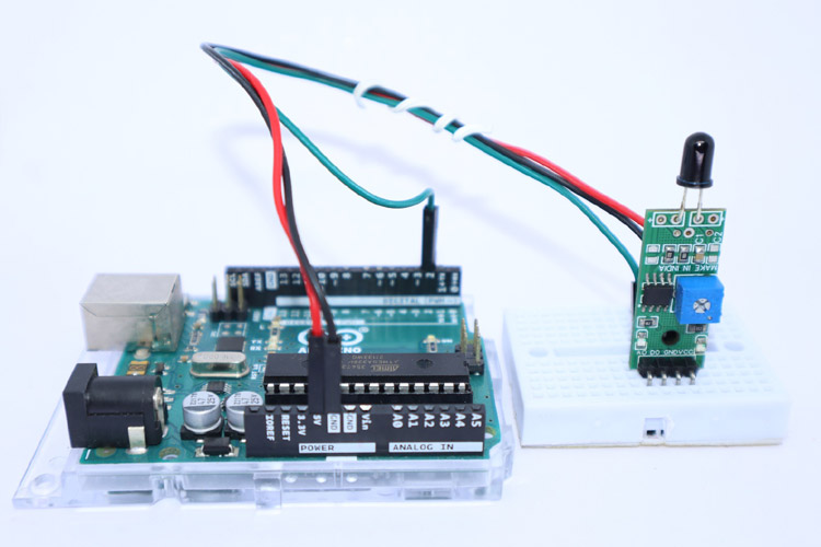
Connections are pretty simple and only require three wires. Connect the VCC and GND of the module to the 5V and GND pins of the Arduino. Then connect the D0 pin to the Arduino’s digital pin 2. We will monitor the state of this pin to detect the fire.
Arduino Flame Sensor Code
The code for interfacing the flame sensor is very simple and easy to understand. We just need to define the pin through which the sensor is connected with the Arduino. Once we do that, we will monitor the status of this pin.
void setup()
{
  pinMode(2, INPUT); //initialize Flame sensor output pin connected pin as input.
  pinMode(LED_BUILTIN, OUTPUT);// initialize digital pin LED_BUILTIN as an output.
  Serial.begin(9600);// initialize serial communication @ 9600 baud:
}
In the setup function, we have initialized the digital pin 2 as input. This pin is used to monitor the flame sensor output. Next, we have initialized pin 13, to which the built-in LED is connected, as an output. We will use this built-in LED as a status indicator. Then we initialized the serial port at a baud rate of 9600.
void loop()
{
  if (digitalRead(2) == 1 )
  {
    digitalWrite(LED_BUILTIN, HIGH); // Led ON
    Serial.println("** Warning!!!!   Fire detected!!! **");
  }
  else
  {
    digitalWrite(LED_BUILTIN, LOW); // Led OFF
    Serial.println("No Fire detected");
  }
  delay(100);
}
In the Loop function, we will monitor the state of digital pin 2. When this pin is pulled low or high by the flame sensor, we will change the state of the status LED and we will print a warning message to the serial monitor.
The below GIF shows the flame sensor interface in action.
Interesting Fire Safety Projects using Arduino
In this project, the intention is to build a Forest fire detection system using IoT which would detect the fire and send an emergency alert to Authority through IoT.
In this project, we will learn how to build a simple robot using Arduino that could move towards the fire and pump out water around it to put down the fire. It is a very simple robot that would teach us the underlying concept of robotics
Supporting Files
void setup()
{
  pinMode(2, INPUT); //initialize Flame sensor output pin connected pin as input.
  pinMode(LED_BUILTIN, OUTPUT);// initialize digital pin LED_BUILTIN as an output.
  Serial.begin(9600);// initialize serial communication @ 9600 baud:
}
void loop()
{
  if (digitalRead(2) == 0 )
  {
    digitalWrite(LED_BUILTIN, HIGH); // Led ON
    Serial.println("** Fire detected!!! **");
  }
  else
  {
    digitalWrite(LED_BUILTIN, LOW); // Led OFF
    Serial.println("No Fire detected");
  }
  delay(100);
}

