A Hall effect sensor or Hall sensor is a magnetic non-contact sensor that generates an electrical signal proportional to the magnetic field applied to it. Hall effect sensors are widely used in industrial applications like current-sensing, position detection, and contactless switching. They are basically like a small reed switch, and when a magnetic field is around, the output voltage will vary according to the magnetic flux. Hall effect sensors are used in BLDC applications because they are robust, accurate, and low failure rate.
This tutorial will see how we can interface the Hall effect sensor with Arduino. The module we are going to use can be operated in either analog mode or digital output mode. We will monitor the module’s output and will change the Arduino onboard LED state according to it.
Hall Effect Sensor Pinout
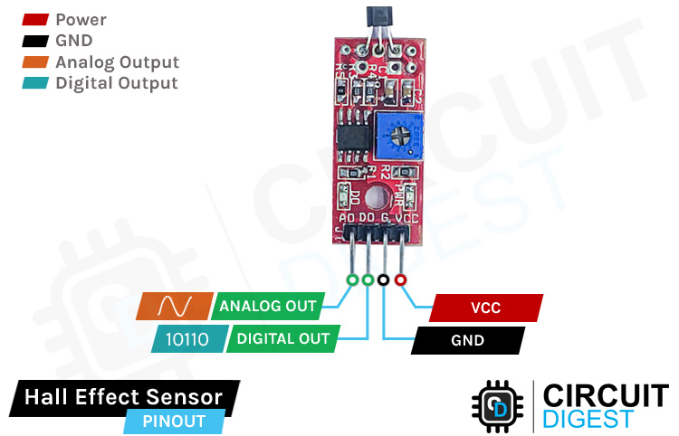
The Hall effect sensor module has 4 pins VCC, GND, DO, and AO. We can either use the AO pin as an output for analog reading or the DO pin as an output for digital readout. The pinout of the Hall effect sensor is as follows:
VCC is the power supply pin for the Hall effect sensor which we connect to the 5V pin on the Arduino.
Ground is the ground pin of the module and it should be connected to the ground pin of the Arduino.
DOUT is the Digital output pin of the board, low output indicates that there is no magnetic field near the sensor, and high indicates the presence magnetic field near the sensor.
AOUT is the Analog output pin of the board that will give us an analog reading directly from the 49E sensor.
How Does a Hall Effect Sensor Module Work?
Hall effect sensors work on the principle of the Hall effect. These sensors consist of a thin piece of rectangular p-type semiconductor material like Gallium Arsenide, Indium Arsenide, Silicon, etc. This p-type semiconductor material is called the Hall element. Continuous current allowed to flow through the Hall element. When the device is placed within a magnetic field, the magnetic flux lines exert a force on the semiconductor material which deflects the charge carriers, electrons, and holes, to either side of the semiconductor. This movement of charge carriers is a result of the magnetic force they experience passing through the semiconductor material. As these electrons and holes move sidewards a potential difference is produced between the two sides of the semiconductor material by the build-up of these charge carriers. Then the movement of electrons through the semiconductor material is affected by the presence of an external magnetic field that is at right angles to it and this effect is greater in a flat rectangular shaped material. The effect of generating a measurable voltage by using a magnetic field is called the Hall Effect.
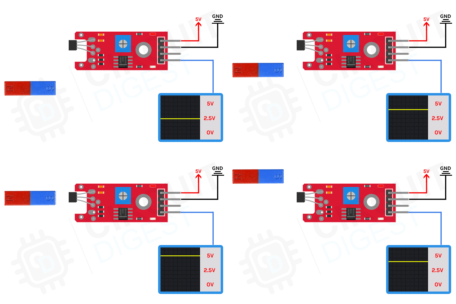
The analog output sits around 50% of VCC when there is no magnetic field. Any magnetic field will cause this value to increase or decrease depending on whether the south or north pole of the magnet is coming near to the sensor. The magnet’s south pole will cause the analog output to linearly ramp towards VCC. If the north pole is introduced, the voltage will decrease linearly up to a minimum value of 0.86V. The amount of voltage change will depend on the strength of the magnetic field.
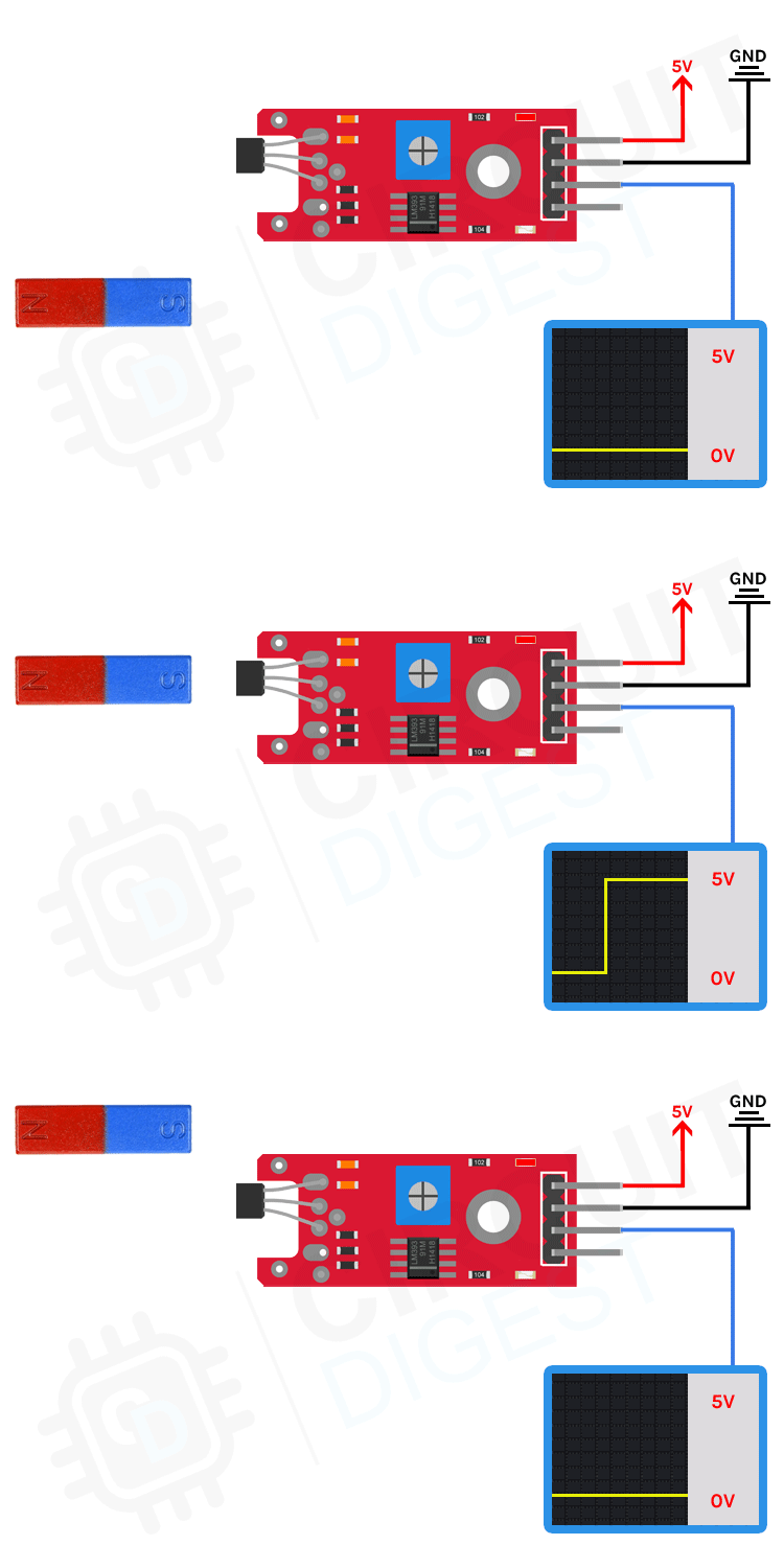
The digital output is active HIGH. This is taken from a comparator circuit built around the famous LM393 comparator chip. When there is no magnetic field, the DO pin will be low and since the status led is between the output and VCC, the LED will be on. When a magnetic field is introduced the DO pin becomes HIGH and the status LED turns off.
Types of Hall Effect Sensor
The main classification of the Hall effect sensor is based on the output signal type – analog output Hall effect sensor and Digital output Hall effect sensor.
Analog Output Hall Effect Sensor
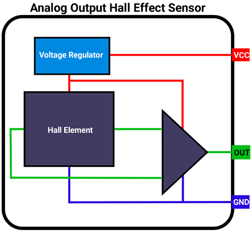
The analog output Hall effect sensor contains a voltage regulator, a Hall element, and a differential amplifier. This type of sensor gives analog output proportional to the magnetic field strength. If the Hall voltage is measured when no magnetic field is present, the output voltage will be zero. But if the voltage at each output terminal of the Hall element is measured with respect to the ground, a non-zero voltage will appear and this voltage will be the same at each output terminal. This voltage is known as common-mode voltage. A differential amplifier is used to eliminate this common-mode voltage. 49E is an example of these types of sensors.
Digital Output Hall Effect Sensor
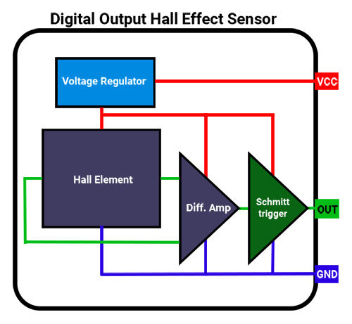
The Analog Output Hall effect sensor can be converted into a digital output sensor by adding a Schmitt trigger at the output of the differential amplifier. The Schmitt trigger compares the output of the differential amplifier with a pre-set value. When the amplifier output exceeds the pre-set value, The Schmitt trigger turns ON. Likewise, when the amplifier output falls below the pre-set value, the Schmitt trigger turns OFF. Thus, this type of sensor has only two output states HIGH or LOW. A3144 is an example of these types of sensors.
The digital output sensors are classified into two categories, based on whether the sensor can detect both south and north polls or not - Unipolar and Bipolar Hall effect sensors.
Unipolar Hall Effect Sensors
This type of sensor can only detect the south pole magnetic fields. WSH130NL and A3144 are some examples of this type of sensor.
Bipolar Hall Effect Sensors
This type of sensor can detect both the south and north magnetic fields and provide a digital output. The output can be turned on (Active LOW) by the south pole and can be turned off by the north pole WSH130 is an example of this type of sensor.
Hall Effect Sensor Module – Parts
This module incorporates an analog Hall Effect sensor. Hall Effect sensors detect the presence of a magnetic field and are commonly used for measuring the RPM of rotating assemblies where a magnet on the assembly alternately makes and breaks magnetic contact with the sensor as the assembly rotates. They can even be used to detect electrical current flow through conductors in some cases.
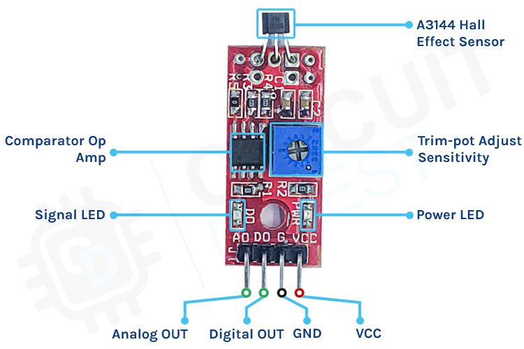
As mentioned earlier, the module consists of the hall sensor itself and a high-precision comparator circuit. The analog out is taken directly from the hall sensor output, which is also connected to a bypass capacitor and a pullup resistor. The comparator circuit is built around the famous LM393 dual comparator chip. It is used to digitize the analog signal from the Hall sensor. The trim-pot is used to adjust the sensitivity.
Commonly Asked Questions about Hall Effect Sensors
What is the input voltage for the Hall Effect Sensor?
The Hall Effect sensor module can be powered by both 3.3V and 5V input supplies. This makes us easier to use it with normal 5V development boards like standard Arduino boards as well as 3.3V microcontrollers like ESP8266 or ESP32.
How to test the Hall effect sensor module?
Testing this module is pretty simple. Connect the input power to VCC and GND. Adjust the trim-pot until the status/DO LED is just turned ON, without any magnetic materials near the sensor. Then simply place a magnet near the sensor and if the LED turns OFF when the magnet is near the sensor, then the module is working fine.
What is the range of these Hall Effect Sensors?
Hall effect sensors have a very low range within a few millimeters. But the exact range will depend on the magnet you are using. The more powerful the magnet, the more sensitive the sensor becomes.
What do the Hall effect sensors sense?
The Hall effect sensors detect the presence and magnitude of the magnetic field. The output voltage of a Hall sensor is directly proportional to the strength of the magnetic field.
Circuit Diagram for Hall Effect Sensor Module
The circuit diagram for the Hall effect sensor module is given below. The circuit itself is pretty simple and only needs a few components.
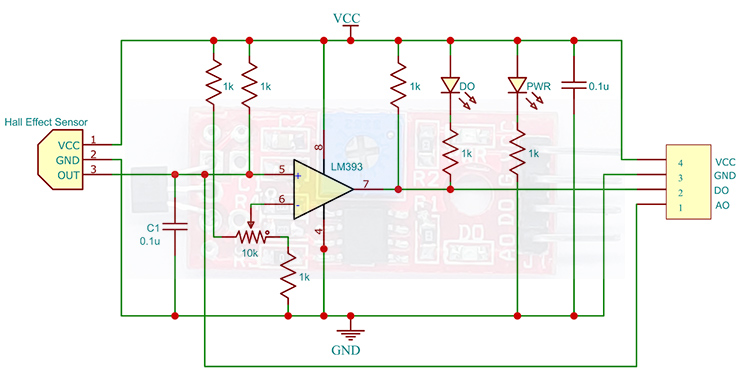
In the schematics, the analog out is directly taken from the Hall effect sensor. And the digital output is processed through the LM393 comparator. The power led is directly connected to the VCC and it will turn on as soon as the power supply is connected. The status led will be on if there is no signal and will turn off when there is a signal at the Digital output pin. The trim-pot is used to set the sensitivity, i.e., at which point the digital out should be high.
Arduino Hall Effect Sensor – Connection Diagram
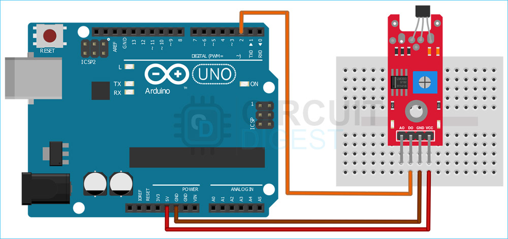
Now let’s connect the module to the Arduino and test it out. For that, make the connections as shown below.
Connections are pretty simple. We can use either digital or analog out from the Hall Effect Sensor module. Here we have used the digital output. Connect the VCC to Arduino’s 5V pin and GND to GND. Next, connect the DO pin to the D2 pin of the Arduino.
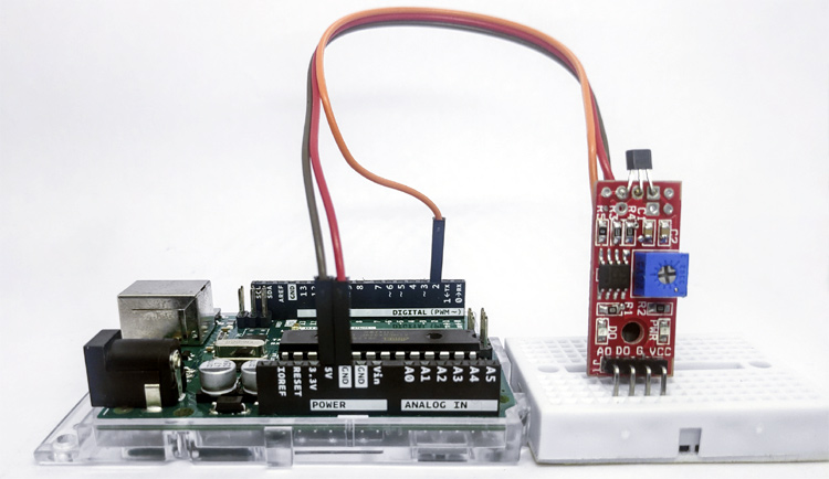
Now with the connection is done, let’s look into the code.
Arduino Code for Interfacing Hall Effect Sensor with Arduino
The Arduino hall effect sensor code is very simple and easy to understand. We will monitor the D2 pin which is connected to the DO pin of the Hall Effect Sensor module, and we will toggle the state of the onboard LED with respect to it i.e., if the sensor output is HIGH, as the sensor detects a magnetic field, the LED will light up and when it’s LOW when there is no magnetic field, the LED will be turned off. Keep in mind that the status LED on the module is inverted, i.e., it will be on when there is no magnetic field and will be off when there is a magnetic field.
We start our code by declaring two global variables to hold the pin values, to which the sensor and the LED are connected. The onboard LED is connected to the D13 pin, so we will be using that.
int HallSensor = 2; // Hall sensor is connected to the D2 pin
int LED = 13; // onboard LED pin
In the setup() function, we will initialize the pins as output or input. The pin to which the sensor is connected is initialized as input. And the LED pin is initialized as output.
void setup() {
  pinMode(HallSensor, INPUT); // Hall Effect Sensor pin INPUT
  pinMode(LED, OUTPUT); // LED Pin Output
}
Next in the loop, we will check the sensor status using the digitalRead function. The state of pin D2 is read and stored in a variable sensorStatus. If the sensor output is HIGH, that means there is a magnetic field near the sensor. To indicate that, we will turn on the onboard LED. If the sensor output is LOW, that means there is no magnetic field present. To indicate that, we will turn off the onboard LED.
Working of the Hall Effect Sensor Module
Here is the GIF that shows the Hall Effect sensor module in action.
Hall Effect Sensor Module Problems and Troubleshooting Steps
The DO/status LED is either always on or always off, not responding to the magnet: Adjust the trim-pot to change the sensitivity and try.
Sensitivity trim-pot is adjusted but still no response: Try changing the magnet pole, some modules come with unipolar sensors.
LED on the module is responsive, but Arduino doesn’t respond: Check the connection for loose contact or short circuit.
Projects Using Hall Effect Sensor
There are some interesting projects done with the Hall Effect Sensor. If you want to know more about those topics, links are given below.
This tutorial provides a step-by-step guide, Circuit Diagram, and complete code to learn how to Interface Hall Sensor with Raspberry Pi.
In this project, we build a Magnetic Polarity Detector using the Hall Sensor and LEDs. Here two Hall Effect sensors are used to detect the North Pole and the South Pole, and these sensors are connected in the opposite direction. Two LEDs are used to indicate the North Pole and the South Pole of a magnet.
Door Alarm Projects are very popular among Electronics students and hobbyists. In this Magnetic Door Alarm circuit, we have used a 555 timer IC in astable mode to generate a tone as an alarm
Supporting Files
int HallSensor = 2; // Hall sensor is connected to the D2 pin
int LED = 13; // onboard LED pin
void setup() {
pinMode(HallSensor, INPUT); // Hall Effect Sensor pin INPUT
pinMode(LED, OUTPUT); // LED Pin Output
}
void loop() {
int sensorStatus = digitalRead(HallSensor); // Check the sensor status
if (sensorStatus == 1) // Check if the pin high or not
{
// if the pin is high turn on the onboard Led
digitalWrite(LED, HIGH); // LED on
}
else {
//else turn off the onboard LED
digitalWrite(LED, LOW); // LED off
}
}

