

As you may know many of our everyday appliances or devices such as smartphones, home automation systems, smart speakers, headphones and many others have their own built-in microphones to capture the audio data. And if we look at them there are different types of microphones available, such as condenser, ribbon, dynamic and MEMS. Most modern devices like smartphones use MEMS microphones for better sensitivity. But the problem with them is that they are digital and will need digital processing to get the audio out of them. On the other hand analog microphones have been there for decades, and they can be found in most devices from cheap toys to high-end studio setups. Among the analog type microphones, the most popular one would be the condenser microphone, they are cheap and easy to interface. But since their output signal is very weak, we will need to do some amplification to the signal before using it. That's where microphone amplifiers come into play.
So, in this article, we will look into such a microphone amplifier module built with the MAX4466 IC, which offers an adjustable gain. We will learn about the basics of MAX4466 microphone amplifier module and how to interface it with an Arduino Board. Previously we have also build many Arduino projects and tutorials here at circuitdigest you can also check them out if you are intrested.
The MAX4466 Microphone Amplifier Module
The MAX4466 microphone amplifier module is a very versatile and easy-to-use microphone amplifier module. As the name suggests it is based on the MAX4466 amplifier chip from Analog Devices. It offers a very high gain of up to 125, adjustable via a potentiometer on the module. This allows users to fine-tune the sensitivity according to their specific application requirements. It also offers an excellent power supply rejection ratio of 112dB and a common mode rejection ratio of 126dB while providing a rail-to-rail output.
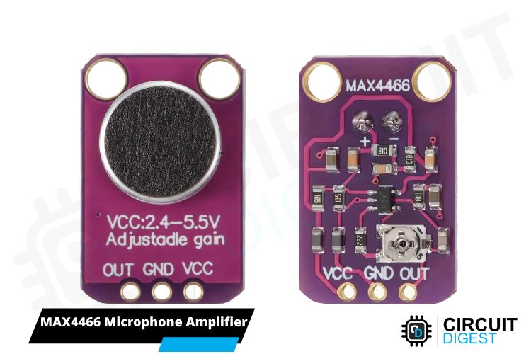
The MAX4466 is capable of delivering a 600kHz AV ≥ 5 gain bandwidth product from only 24µA of supply current. The module also includes an electret microphone capable of capturing audio ranging from 20 Hz to 20 kHz. With all these excellent features the MAX4466 microphone amplifier module is capable of producing exceptional sound quality even in noisy environments.
MAX4466 Microphone Amplifier Module Pinout
The MAX4466 module only has 3 pins, making it very easy to interface. The pins include VCC, GND and OUT. The VCC and GND pins are used for supplying power to the module and the output signal is taken from the OUT Pin.
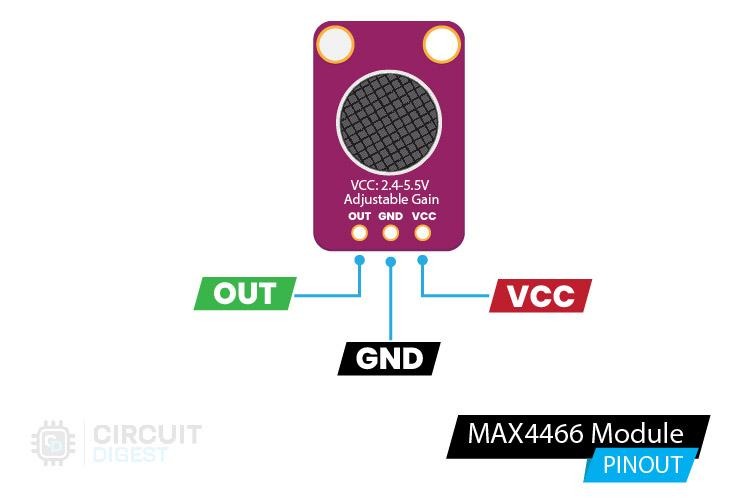
VCC Power supply input for the module. Input range +2.4V to +5.5V.
GND Power supply ground.
OUT Output pin provides amplified signal from the microphone.
MAX4466 Microphone Amplifier Module - Parts
In the below parts marking image, you can see the main components in the module marked. As you can see in the front side there is nothing much but the electret microphone itself.
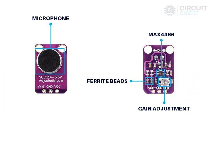
The remaining circuitry is on the back side of the module. Here you can see the MAX4466 amplifier chip along with its complimentary circuitry. A surface mount potentiometer is provided to adjust the gain of the module. You can also find two SMD ferrite beads on the PCB, which are in aeries with the VCC and GND pins. They are there to suppress EMI interference and to enhance the CMRR performance further.
MAX4466 Microphone Amplifier Module Circuit Diagram
The Schematic diagram for the MAX4466 Microphone Amplifier Module is given below. The circuit consists of bare minimum components. As we know the main component is the MAX4466 chip. Along with the MAX4466 chip the circuit consists of the microphone, ferrite beads for noise suppression and other complimentary components for the amplifier chip. It is the same as the typical application diagram provided on the MAX4466 datasheet.

Commonly Asked Questions About MAX4466 Module
Is MAX4466 analog or digital?
The MAX4466 provides an analog output.
What is the frequency range of MAX4466?
The audio signal can be in the frequency range 20 - 20 kHz.
How to adjust gain on MAX4466?
On the back side of the board, a small potentiometer is included for changing the gain. It is possible to set the gain from 25x to 125x.
What is the difference between MAX9814 and MAX4466?
The MAX4466 is quite classical and has an integrated op-AMP and gain can change from 25x to 125x while the MAX9814 has an automatic gain control.
What is the working voltage of MAX4466?
The MAX4466 module can be powered with range of voltage from 2.4V to 5V.
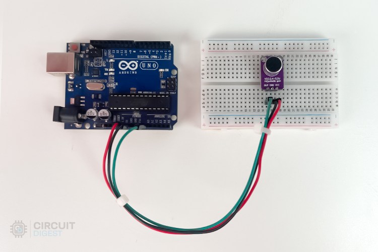
MAX4466 Module Arduino Interfacing Circuit Diagram
For interfacing the MAX4466 module with the Arduino, we will be using an analog pin. Follow the circuit diagram below and make the connections as per that.
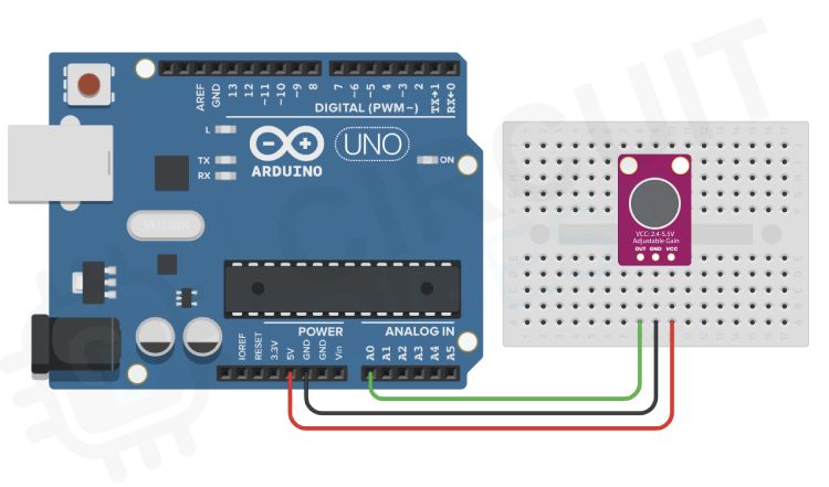
The connection is relatively simple and only requires 3 wires, in which two are for power and one for signal. Connect the VCC pin of the module to the 5V pin on the Arduino and the GND pin to the GND pin on the Arduino. Next connect the OUT pin to the A0 pin of the Arduino.nce the connections are done we can move forward with the coding. Here's how the real-life connection looks.
Arduino MAX4466 Microphone Amplifier Code
In this example we will read the microphone output and the peak values will be plotted on the serial plotter. At first, we have declared all the variables we need as global variables. Next in the setup function we have initialised the serial interface with a baud rate of 9600. We will be sending the peak value over the serial, and this send value will be then plotted on to the Arduino IDE serial plotter.
const int sampleWindow = 50;  // Sample window width in mS (50 mS = 20Hz)
int const Input_Pin = A0;     // Preamp output pin connected to A0
unsigned int ADC_Value;
void setup() {
 Serial.begin(9600);
}
Next in the loop function we will read the ADC values continuously for sample window, in this example 50ms, and then calculate the peak value de detected within this window. This peak value is then send to the PC using the serial print function. You can also see that we have eliminated the value below 20, because its mostly noice. You can also adjust the gain control pot to adjust the sensitivity.
void loop() {
 unsigned long startMillis = millis();  // Start of sample window
 unsigned int PeakValue = 0;  // peak-to-peak level
 unsigned int InMax = 0;
 unsigned int InMin = 1024;

 // collect data for 50 mS and then plot data
 while (millis() - startMillis < sampleWindow) {
   ADC_Value = analogRead(Input_Pin);
   if (ADC_Value < 1024)  // toss out spurious readings
   {
     if (ADC_Value > InMax) {
       InMax = ADC_Value;  // save just the max levels
     } else if (ADC_Value < InMin) {
       InMin = ADC_Value;  // save just the min levels
     }
   }
 }
 PeakValue = InMax - InMin;  // max - min = peak-peak amplitude
 if (PeakValue < 20) {
   PeakValue = 0;
 }
 Serial.println(PeakValue);
}
Now Compile the code and upload it to the Arduino. Open up the serial plotter and you can see when there is a sound the value is plotted to the serial plotter window.
Here’s the GitHub repo where you can find the complete code and the circuit diagrams that we have used in this tutorial.


const int sampleWindow = 50; // Sample window width in mS (50 mS = 20Hz)
int const Input_Pin = A0; // Preamp output pin connected to A0
unsigned int ADC_Value;
void setup() {
Serial.begin(9600);
}
void loop() {
unsigned long startMillis = millis(); // Start of sample window
unsigned int PeakValue = 0; // peak-to-peak level
unsigned int InMax = 0;
unsigned int InMin = 1024;
// collect data for 50 mS and then plot data
while (millis() - startMillis < sampleWindow) {
ADC_Value = analogRead(Input_Pin);
if (ADC_Value < 1024) // toss out spurious readings
{
if (ADC_Value > InMax) {
InMax = ADC_Value; // save just the max levels
} else if (ADC_Value < InMin) {
InMin = ADC_Value; // save just the min levels
}
}
}
PeakValue = InMax - InMin; // max - min = peak-peak amplitude
if (PeakValue < 20) {
PeakValue = 0;
}
Serial.println(PeakValue);
}
Comments
Yes, you can use the Nano…
Yes, you can use the Nano instead. The MAX4466 outputs an analog signal so you can use any board with an ADC.
I should add that I the…
I should add that I the Arduino would have to have a card slot for storing audio files. Thanks!
Thanks, working on uploading…
Thanks, working on uploading it now!
Awesome, it worked once I…
Awesome, it worked once I deleted the redundant void loop() { at the beginning of the file. Now I have to figure out how to save the audio to SD card and then have it erase the oldest audio files and replace with the newest (like a dashcam). Thanks for posting!

Great article, thanks for posting. If I want to connect the MAX4466 to an Arduino with a smaller form factor, are there any that are more suitable than others? For example, would the Nano be better than the MKR Zero?