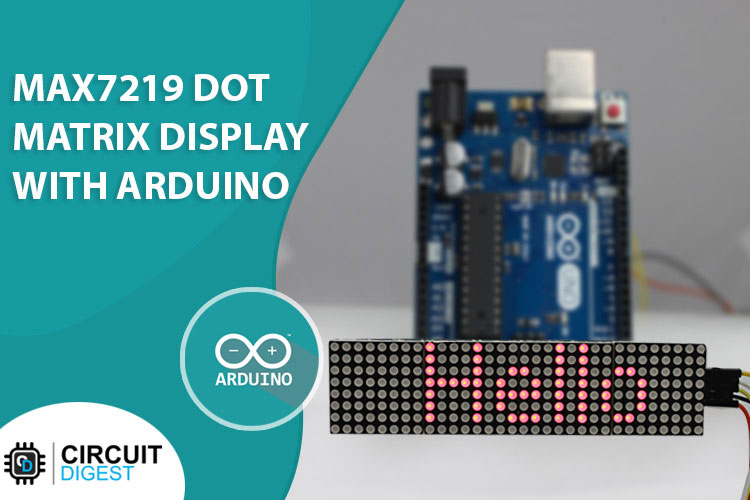
When it comes to adding a display to your next project there are many options to choose from like OLED, 16x2 LCD, Seven Segment, and E-Paper Display. But there exists another type of display that I feel is mostly ignored due to the lack of coverage by enthusiasts and hobbyists on the internet. So in this article, we decided to shed some light on this cheap and easy-to-use display called Dot Matrix Display, and for this project, we will be interfacing Arduino with Dot Matrix Display. We have previously built some attractive projects using this dot matrix display like an Arduino Audio Visualizer, Bluetooth Controlled LED Matrix Display and even an Arduino Snake Game, you can check them out if you are interested.
MAX7219 8x8 Dot Matrix LED Module Overview
When we are talking about the MAX7219 8x8 LED Matrix Display module there are two versions available, one is the generic one, and the other is the FC-16 module. Both of these modules are discussed below.
The Dot Matrix Display
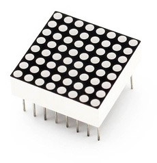
When we are talking about the MAX7219-based dot matrix display module, it consists of 64 LEDs connected in a row-column format so that we could easily control them with the multiplexing technique. That is why a typical single color 8×8 dot matrix unit has 16 pins, 8 for each row and 8 for each column. An image of a dot matrix display is shown below.
MAX7219 Chip 8-Digit LED Display Driver
The MAX7219 chip is a serial input/output common-cathode display drivers IC that can interface microprocessor to 7-segment numeric LED display of up to 8-digit and a bar graph display of 64 individual LEDs. The MAX7221 is compatible with SPI, QSPI, and MICROWIRE, and has slew rate-limited segment drivers to reduce EMI.

The most common problem with multiplexing is that your microcontroller will always be busy refreshing the display and will not have the time to do other tasks. But with the help of MAX7219, you don't need to worry about refreshing the display because this IC also takes care of that part. You just need to send serial data through SPI and it will automatically take care of the rest.
The MAX7219 can fully control 64 individual LEDs and it can simultaneously update the display with 800 Hz refresh rate, other than that if you need to control the brightness of the LEDs it has the option to do so with hardware and software. And it can do it simultaneously without interrupting the microcontroller.
Setting the brightness of the display with MAX7219 Display Driver IC
The MAX7219 display chip allows you to control the brightness of the display through hardware or software. If you want to set the brightness of the LED, this module comes with a brightness-adjusting resistor at the bottom of the board.

The resistor is responsible for setting the upper limit of the current therefore limiting the overall brightness of the LEDs. The following table shows the values of the resistor that you should use according to the voltage and forward current for your LED matrix. e.g. if you have a 2.5V 10 mA LED, your resistor value will be 59.3kΩ

We will adjust the brightness of the LED through software later in the article.
MAX7219 Based LED Dot Matrix Display Module Pinout
The pinout of the MAX7219-based dot matrix display is shown below. It has five significant pins: VCC, GND, DIN, CS, and SCK. All the pins of this sensor module are digital, except VCC and Ground, and the device can operate at only 5V volts. If you are using it in full brightness you can provide 1A of current to power the LEDs.
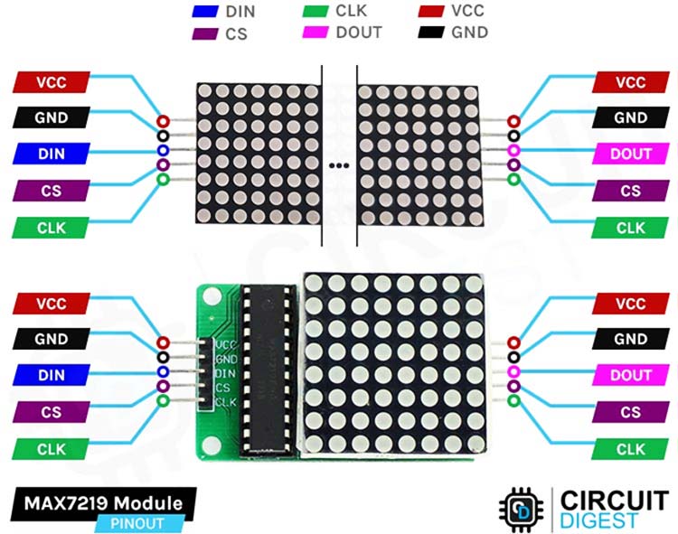
VCC connects to a 5V power supply. But do keep note that the module consumes 1A of current so it's recommended that you use a 5V external power supply.
GND This is the Ground pin of the module, connect it to any pin of the microcontroller.
DIN is the Data In pin, connect it to any digital pin of the microcontroller.
CS/LOAD is the chip select pin of the module, connect it to any digital pin of the Arduino
CLK CLK is the clock pin of the module, connect it to any digital pin of the Arduino
How Does a 8x8 Dot Matrix Display Work?
The working of the dot matrix display is very simple and easy to understand. The technique used to display a pattern or letter on the screen is known as multiplexing. In this technique, each column is powered up for a certain period of time and the switching happens so fast ( thousands of times a second) that the persistence of the human eye perceives the display to be fully lit. This process is shown in the gif below.
MAX7219 LED Dot Matrix Display Module - Parts
The parts marking of both the dot matrix display is shown below, and as you can see from the image below, there is not much on the board.
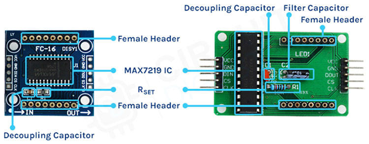
On the PCB, there is nothing much except the MAX7291 IC. There are a pair of male headers on the PCB, one is for data-in and another is for data-out. The data out pin is there to daisy chain the module with other modules, also there is a pair of female connectors that is used to place the display module. Other than that, there is a filter capacitor and a decoupling capacitor on the board. Finally, you can see one of the most important parts of the PCB which is the current limiting resistor through which you can set the brightness of the connected LEDs or the display.
Commonly Asked Questions about the MAX7219 LED Dot Matrix Display Module
What is the purpose of MAX7219 pin 18?
This pin is used to set the output current by connecting a resistor at this pin whose other terminal is connected to the ground. This resistor is used to adjust the value of the current.
What is a matrix LED display?
"Dot Matrix" is a unique category of LED Displays and is also found in LCD and OLED products. The concept of LED Dot Matrix Display is the same as LCD Dot Matrix and OLED Dot Matrix. It is able to show characters, numbers, or graphics by lighting up different pixels(dots) of a Display.
How do you control the MAX7219 LED matrix with the ESP8266 WIFI module?
The process is very simple, as the MAX7219 IC communicates with SPI, and with the QSPI bus, you can connect it directly to the SPI bus of the ESP8266.
MAX7219 LED Dot Matrix Display Module Circuit Diagram
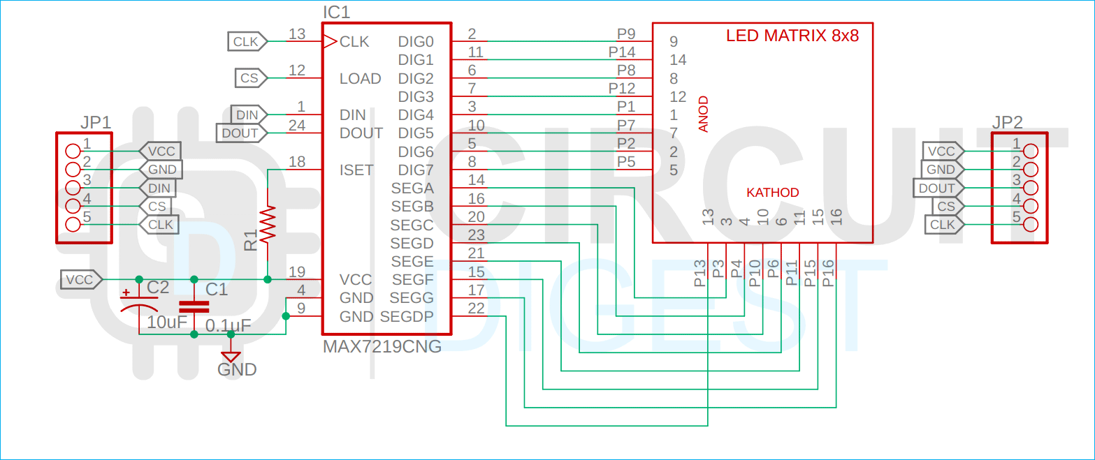
The module is very generic and can be made with genetic components, most of which you can find in your local hobby store. The schematic diagram of the MAX7219-based dot matrix display module is shown below.
As you can see in the above diagram, there is not anything complicated about the schematic. The control line for the segments and digits are connected as per the datasheet of MAX7219. Other than that, a filter and a decoupling capacitor are connected to the power line as they are recommended for power line filtration. And finally, the current limiting resistor needs to be set by the user to adjust the brightness.
ACircuit Diagram to Interface LED MAtrix display with Arduino
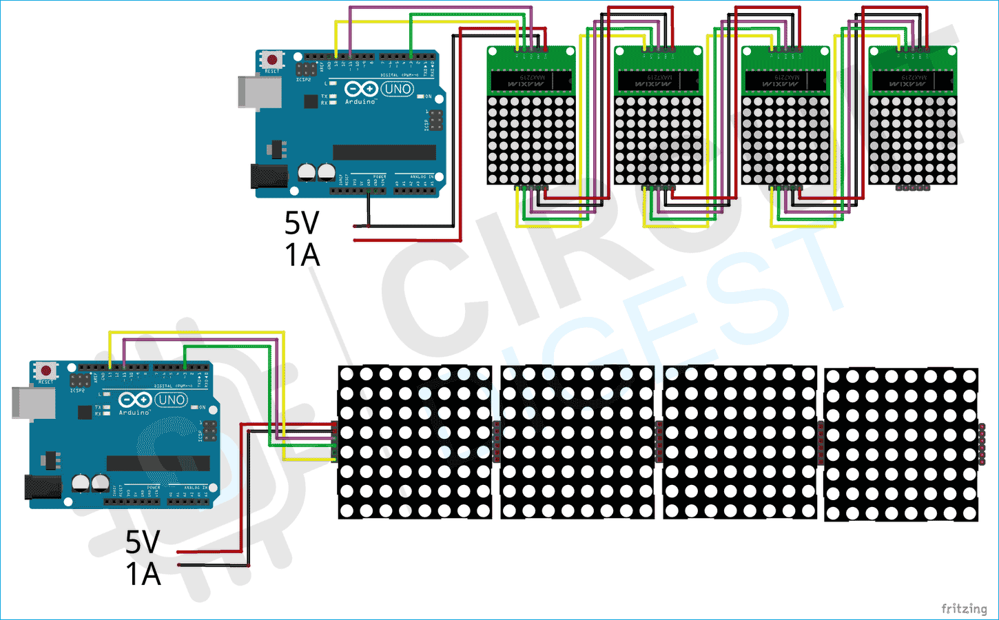
Now that we have completely understood how a MAX7219 LED Dot Matrix Display Module works, we can connect all the required wires to the Arduino and write the code to print our desired text on the display. The connection diagram of the MAX7219 dot matrix display is shown below.
Connecting the MAX7219 module is very simple; if you have the FC-16 module, you just need to connect four wires to the Arduino and connect 5V 1A external power to the module, and you are done. Now you have to adjust everything in the software.
Connecting the MAX7219 single module is a little bit difficult because you need to connect the dout pin of a module to the Din pin of another module simultaneously, connecting the clock and data pins to the Arduino and other modules.
Once everything is connected the hardware looks like the image shown above.
Arduino Code for Interfacing MAX7219 LED Matrix Module with Arduino
The code required to interface the SIM800L with Arduino is very simple and easy to understand.
The code uses the SPI bus along with a chip select line to control the display module. For that code to work properly you need to install the required library in the Arduino environment, those are the MD_MAX72XX library and MD_Parolaby library by marco. Once you first install these libraries with the help of the library manager we are good to go.
We start our code by including all the required libraries, and we will also define the hardware type, number of modules, and the chip select pin.
// Including the required Arduino libraries
#include <MD_Parola.h>
#include <MD_MAX72xx.h>
#include <SPI.h>
// Uncomment according to your hardware type
#define HARDWARE_TYPE MD_MAX72XX::FC16_HW
//#define HARDWARE_TYPE MD_MAX72XX::GENERIC_HW
// Defining size, and output pins
#define MAX_DEVICES 1
#define CS_PIN 3
Next, we will create a new instance of the md parola library.
MD_Parola myDisplay = MD_Parola(HARDWARE_TYPE, CS_PIN, MAX_DEVICES);
Next, we have our setup() function under which we will initialize the instance with the begin method. Next, we will set the intensity of the display, and finally we will clear the display that marks the end of the setup function.
void setup() {
  // Initialize the object
  myDisplay.begin();
  // Set the brightness of the display (0-15)
  myDisplay.setIntensity(2);
  // Clear the display
  myDisplay.displayClear();
}
Next, we have our loop function. In the loop function, we will set the alignment, print the character, and add a delay of 1000. We will do this for all the letters we want to print. In our case, we are printing the circuit digest text on the display.
void loop() {
  myDisplay.setTextAlignment(PA_LEFT);
  myDisplay.print("C");
  delay(650);
  myDisplay.setTextAlignment(PA_LEFT);
  myDisplay.print("I");
  delay(650);
  myDisplay.setTextAlignment(PA_LEFT);
  myDisplay.print("R");
  delay(650);
  myDisplay.setTextAlignment(PA_LEFT);
  myDisplay.print("C");
  delay(650);
  myDisplay.setTextAlignment(PA_LEFT);
  myDisplay.print("U");
  delay(650);
  myDisplay.setTextAlignment(PA_LEFT);
  myDisplay.print("I");
  delay(650);
  myDisplay.setTextAlignment(PA_LEFT);
  myDisplay.print("T");
  delay(650);
  myDisplay.setTextAlignment(PA_LEFT);
  myDisplay.print("D");
  delay(650);
  myDisplay.setTextAlignment(PA_LEFT);
  myDisplay.print("I");
  delay(650);
  myDisplay.setTextAlignment(PA_LEFT);
  myDisplay.print("G");
  delay(650);
  myDisplay.setTextAlignment(PA_LEFT);
  myDisplay.print("E");
  delay(650);
  myDisplay.setTextAlignment(PA_LEFT);
  myDisplay.print("S");
  delay(650);
  myDisplay.setTextAlignment(PA_LEFT);
  myDisplay.print("T");
  delay(1500);
}
This marks the end of the code for the single display module. Now we can check out the code for the FC16 module.
For the FC16 module, we will make a scrolling display and the code for the scrolling display is mostly the same so in this portion of the article, we will mention only the changes that are done to the code.
First, you need to change the hardware type.
#define HARDWARE_TYPE MD_MAX72XX::FC16_HW
Next, we have to change the MAX_DEVICES to four, so that the code recognizes we are working with 4 displays.
#define MAX_DEVICES 4
Next in the setup function, we need to add in the extra line that is written below. This configures the MAX7219 IC to act as a scrolling display.
myDisplay.displayScroll("Hello", PA_CENTER, PA_SCROLL_LEFT, 100);
Finally, in the loop() function we need to call the displayAnimate() and the displayReset() function so that the scrolling continues to loop()
void loop() {
  if (myDisplay.displayAnimate()) {
    myDisplay.displayReset();
  }
Working of the MAX7219 8x8 Dot Matrix with Arduino
The video below shows the working of the MAX7219 module, as we are using two types of display, there will be two codes as you can see in the code section. First, we will upload the code for the single MAX7219 module which will print CIRCUIT DIGEST on the display one letter at a time.
For the FC-16 module, we have used the hello example of the library and made a scrolling display out of it as you can see in the video below.
Projects using Arduino and MAX7219 LED Dot Matrix Display Module
As the MAX7219 is a Matrix display so if you want to learn the basics about LED matrix, you can check the project of basics on the LED matrix where we have discussed all the details about LED multiplexing.
If you are trying to interface the MAX7219 Module with Raspberry, then you need not have to go any further than this because in this article we have done just that. And as a bonus, we have also used the led module only to print characters on the display.
If you are trying to interface the MAX7219 module with STM8S microcontroller, then you absolutely need to check out this project because in this project we have used the STM8S microcontroller to do just that.
// Including the required Arduino libraries
#include <MD_Parola.h>
#include <MD_MAX72xx.h>
#include <SPI.h>

// Uncomment according to your hardware type
#define HARDWARE_TYPE MD_MAX72XX::FC16_HW
//#define HARDWARE_TYPE MD_MAX72XX::GENERIC_HW

// Defining size, and output pins
#define MAX_DEVICES 1
#define CS_PIN 3

// Create a new instance of the MD_Parola class with hardware SPI connection
MD_Parola myDisplay = MD_Parola(HARDWARE_TYPE, CS_PIN, MAX_DEVICES);

void setup() {
  // Intialize the object
  myDisplay.begin();

  // Set the brightness of the display (0-15)
  myDisplay.setIntensity(2);

  // Clear the display
  myDisplay.displayClear();
}

void loop() {
  myDisplay.setTextAlignment(PA_LEFT);
  myDisplay.print("C");
  delay(650);

  myDisplay.setTextAlignment(PA_LEFT);
  myDisplay.print("I");
  delay(650);

  myDisplay.setTextAlignment(PA_LEFT);
  myDisplay.print("R");
  delay(650);

  myDisplay.setTextAlignment(PA_LEFT);
  myDisplay.print("C");
  delay(650);

  myDisplay.setTextAlignment(PA_LEFT);
  myDisplay.print("U");
  delay(650);

  myDisplay.setTextAlignment(PA_LEFT);
  myDisplay.print("I");
  delay(650);

  myDisplay.setTextAlignment(PA_LEFT);
  myDisplay.print("T");
  delay(650);

  myDisplay.setTextAlignment(PA_LEFT);
  myDisplay.print("D");
  delay(650);

  myDisplay.setTextAlignment(PA_LEFT);
  myDisplay.print("I");
  delay(650);

  myDisplay.setTextAlignment(PA_LEFT);
  myDisplay.print("G");
  delay(650);

  myDisplay.setTextAlignment(PA_LEFT);
  myDisplay.print("E");
  delay(650);


  myDisplay.setTextAlignment(PA_LEFT);
  myDisplay.print("S");
  delay(650);


  myDisplay.setTextAlignment(PA_LEFT);
  myDisplay.print("T");
  delay(1500);
}
