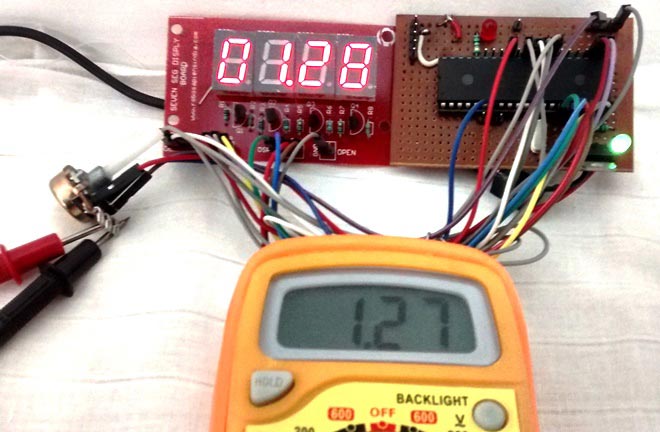
If you are thinking about building your next project around a 4-digit seven-segment display, you need at least 12 connecting pins to drive all the segments properly, that is most of the pins for a microcontroller like Arduino. The workaround for this problem comes in the form of an IC, and as the title of the project suggests it's called TM1673 LED Drive Control. So for this project, we will be using a ready-to-use TM1637 Based 4 Bits Red Digital Tube LED Display Module and will be testing its every feature and also in the end we will give you a working video of the model. In our previous article, we used seven segment displays to build Clock, counter, stopwatch timer, and more. You can check out those, if you are interested.
TM1637 IC Basic Features
TM1637 is a kind of LED (light-emitting diode display) drive controller special circuit with a keyboard scan interface. It is internally integrated with MCU digital interface, data latch, and LED high-pressure drive. Other than that, this IC also has the capability to control the brightness of the display, which means the display can be dimmable if it's required for the project. This device comes in a DIP and SOIC package and can be used for many different applications like display drives of induction cookers, microwave ovens, and small household electrical appliances.
Other than the banner feature, the TM1637 has some interesting features that can make the coding process a lot easier. You can serial upload the display data in the IC, and the IC takes care of refreshing the display, reducing the overhead from the microcontroller. Now if you take a close look at the display module, it features a ‘colon’ that can be used for timer-based projects. The operating voltage for this module is 3.3V to 5V and for the communication process, it uses a two-wire bus rather than the I2C bus so if you are writing a library for this device you need to take note of that. For more information on the IC, you can check the TM1637 7-Segment display driver datasheet IC.
TM1637 Seven Segment Display Module Pinout
The pinout of the TM1637 4-digit Seven Segment Display is shown below. It has 4 pins those are CLK, DIO, VCC, and GND. All the pins of this sensor module are digital, except VCC and Ground, and the device can operate in the 3.3V to 5V voltage range. The Pinout of seven segment display module is shown below:
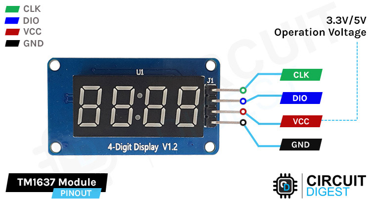
CLK is a clock input pin. Connect to any digital pin on Arduino Uno.
DIO is the Serial Data I/O pin. Connect to any digital pin on Arduino Uno.
VCC pin supplies power to the module. Connect it to the 3.3V to 5V power supply.
GND is a ground pin.
TM1637 Seven Segment Display Module Parts
The TM1637 module is a low-power, low-cost display module that can be used for many different applications. The parts marking of the TM1637 4-Digit 7-Segment Display Module is shown below.
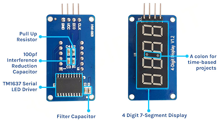
The TM1637 module consists of two parts; the first is a 4-digit 7-segment display and the second one is the TM1637 7-Segment Display Driver IC. The IC supports many functionalities including on-off and brightness control. This IC also has a data queue which means that you can send all the data packets to the IC and the IC will display all the information sequentially, giving headroom to your microcontroller for other tasks.
Commonly Asked Questions
Q. What is TM1637 IC?
TM1637 is a kind of LED (light-emitting diode display) drive control special circuit with a keyboard scan interface and it's internally integrated with MCU digital interface, data latch, LED high-pressure drive, and keyboard scan.
Q. Is TM1637 an I2C?
No, the TM1637 does not use I2C, it uses a digital interface so any digital pin of a microcontroller can drive this display without any issues.
Q. How many types of 7-segment displays are there and what is the TM1637 Module Use?
There are two types of LED 7-segment displays: common cathode (CC) and common anode (CA). The difference between the two displays is that the common cathode has all the cathodes of the 7-segments connected directly together and the common anode has all the anodes of the 7-segments connected together. The TM1637 module uses a common cathode display.
TM1637 4-Digit 7-Segment Display Module Circuit Diagram
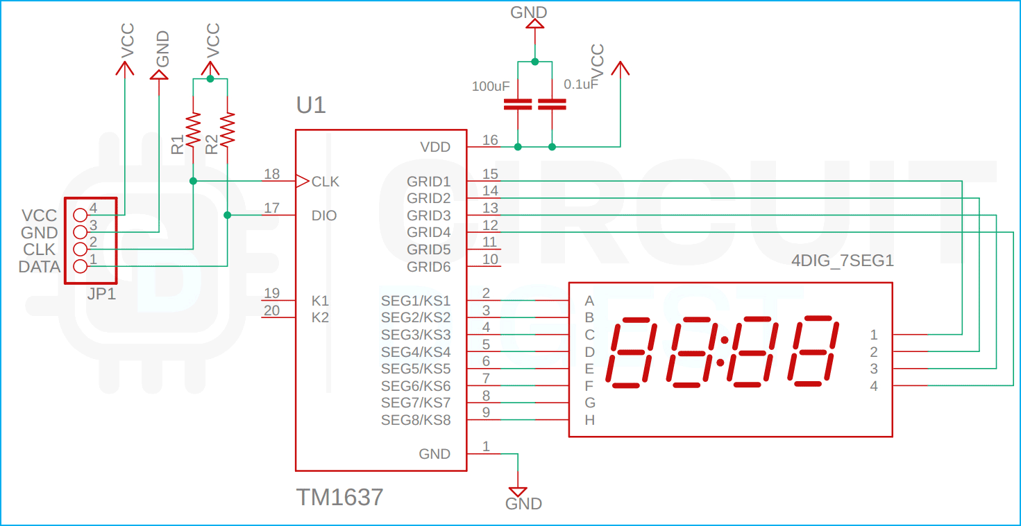
The circuit diagram of the 4-digit 7-segment display is very simple and needs a couple of components to work properly. The main component of the module is the TM1637 IC and the display module. Other than that, we need 4 capacitors and two resistors and that's all for the components required to build the circuit. The complete schematic diagram of the TM1637 Module is shown below.
Arduino and TM1637 4-Digit 7-Segment Display Circuit Diagram
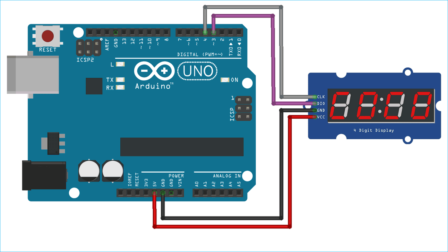
Now that we have completely understood how a TM1637 seven-segment display driver IC works, we can connect all the required wires to Arduino Uno and write the code to get all the data out from the sensor. The Circuit Diagram of the TM1637 module with Arduino is shown below-
Connecting the TM1637 seven-segment display module with the Arduino is very simple. To communicate with the module we just need to connect the power lines to the 3.3V or 5V pin of the Arduino Uno and we are connecting the data line to the digital pin 3 and digital pin 4 of the Arduino Uno.
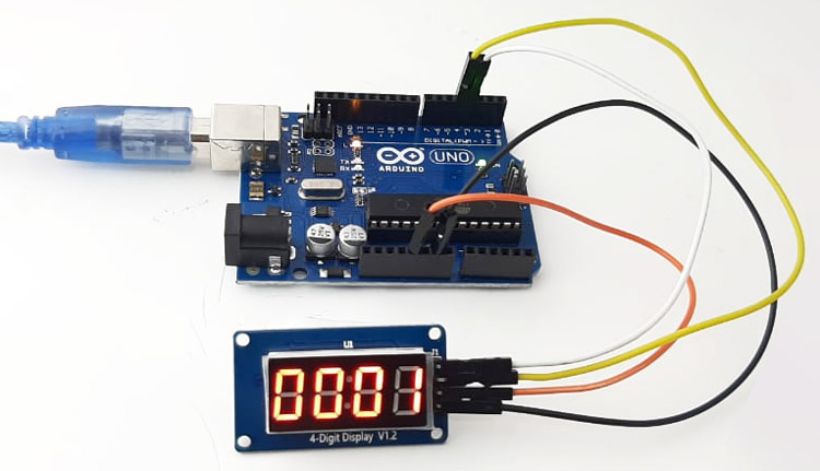
Code for Interfacing TM1637 4-Digit 7-Segment Display Module with Arduino
The code to process the display data to the TM1637 display is very simple and easy to understand. We just need to define the pins through which the 7-segment display module is connected to the Arduino and other things will be handled by the Arduino TMS1637 Library. For demonstration purposes, we will be using the example code of the library.
So we start our code by including all the required libraries and we define the CLK and DIO pin. We'll also define the delay between every test.
#include <Arduino.h>
#include <TM1637Display.h>
// Module connection pins (Digital Pins)
#define CLK 3
#define DIO 4
// The amount of time (in milliseconds) between tests
#define TEST_DELAY   2000
Then we define an array, in this arry the word dOnE is stored.
const uint8_t SEG_DONE[] = {
            SEG_B | SEG_C | SEG_D | SEG_E | SEG_G,           // d
            SEG_A | SEG_B | SEG_C | SEG_D | SEG_E | SEG_F,   // O
            SEG_C | SEG_E | SEG_G,                           // n
            SEG_A | SEG_D | SEG_E | SEG_F | SEG_G            // E
            };
Next, we initialize an object name display and pass the CLK and DIO pins in that instance.
TM1637Display display(CLK, DIO);
Next, we have our setup() function. In the setup() function, we don't need to assign anything because all the major operations happen in the loop section.
void setup() {
  // Intialize the object
  myDisplay.begin();
  // Set the brightness of the display (0-15)
  myDisplay.setIntensity(2);
  // Clear the display
  myDisplay.displayClear();
}
Next, we have the void loop() function. In the loop() function, the code is written as such that it will go through a set of sequences and display a lot of characters sequentially. We start off our loop() function by defining a variable that will be used for the loop counter later in the code. Next, we have two arrays. The first data array is to light up all the segments and the dots and the second blank array will be used to turn off the display. And the setBrightness() function will be used to set the brightness of the display.
  int k;
  uint8_t data[] = { 0xff, 0xff, 0xff, 0xff };
  uint8_t blank[] = { 0x00, 0x00, 0x00, 0x00 };
  display.setBrightness(0x0f);
Next, we turn on all the segments and add a predefined delay.
 // All segments on
  display.setSegments(data);
  delay(TEST_DELAY)
Now the next portion of the code is there to display the 0 1 2 3 digits on the seven-segment display.
  // Selectively set different digits
  data[0] = display.encodeDigit(0);
  data[1] = display.encodeDigit(1);
  data[2] = display.encodeDigit(2);
  data[3] = display.encodeDigit(3);
  display.setSegments(data);
  delay(TEST_DELAY);
The next portion of the code prints No 23 on the display.
  display.clear();
  display.setSegments(data+2, 2, 2);
  delay(TEST_DELAY);
  display.clear();
  display.setSegments(data+2, 2, 1);
  delay(TEST_DELAY);
  display.clear();
  display.setSegments(data+1, 3, 1);
  delay(TEST_DELAY);
The next portion of the code displays numbers without leading zeros.
// Show decimal numbers with/without leading zeros
  display.showNumberDec(0, false); // Expect: ___0
  delay(TEST_DELAY);
  display.showNumberDec(0, true);  // Expect: 0000
  delay(TEST_DELAY);
            display.showNumberDec(1, false); // Expect: ___1
            delay(TEST_DELAY);
  display.showNumberDec(1, true);  // Expect: 0001
  delay(TEST_DELAY);
  display.showNumberDec(301, false); // Expect: _301
  delay(TEST_DELAY);
  display.showNumberDec(301, true); // Expect: 0301
  delay(TEST_DELAY);
  display.clear();
  display.showNumberDec(14, false, 2, 1); // Expect: _14_
  delay(TEST_DELAY);
  display.clear();
  display.showNumberDec(4, true, 2, 2);  // Expect: 04__
  delay(TEST_DELAY);
  display.showNumberDec(-1, false);  // Expect: __-1
  delay(TEST_DELAY);
  display.showNumberDec(-12);        // Expect: _-12
  delay(TEST_DELAY);
  display.showNumberDec(-999);       // Expect: -999
  delay(TEST_DELAY);
  display.clear();
  display.showNumberDec(-5, false, 3, 0); // Expect: _-5_
  delay(TEST_DELAY);
  display.showNumberHexEx(0xf1af);        // Expect: f1Af
  delay(TEST_DELAY);
  display.showNumberHexEx(0x2c);          // Expect: __2C
  delay(TEST_DELAY);
  display.showNumberHexEx(0xd1, 0, true); // Expect: 00d1
  delay(TEST_DELAY);
  display.clear();
  display.showNumberHexEx(0xd1, 0, true, 2); // Expect: d1__
  delay(TEST_DELAY);
The next portion of the code controls the brightness of the display. If you are looking for how you can control the brightness of the TM1637 display you can refer to this portion of the code.
// Brightness Test
  for(k = 0; k < 4; k++)
            data[k] = 0xff;
  for(k = 0; k < 7; k++) {
    display.setBrightness(k);
    display.setSegments(data);
    delay(TEST_DELAY);
  }
The next portion of the code does the ON/OFF test.
// On/Off test
  for(k = 0; k < 4; k++) {
    display.setBrightness(7, false);  // Turn off
    display.setSegments(data);
    delay(TEST_DELAY);
    display.setBrightness(7, true); // Turn on
    display.setSegments(data);
    delay(TEST_DELAY);
  }
Finally, we print the dOnE message that we have defined at the start of the code. If you see the done message in the display, you will know that it has gone through the full loop.
Arduino TM1637 Display Module Working
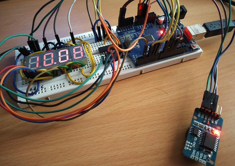
The video below shows the hardware circuitry of the TM1637 seven-segment display driver Arduino in action. We have programmed the Arduino with the example test code that updates the display with new data over a certain period of time. And as you can see in the gif below, the display is changing characters once every 20 seconds and at the end, you can see the dimming function in action.
Error in Interfacing TM1637 4-Digit 7-Segment Display? - Here is what you Should do
If you are having trouble working with the TM1637 module, you first need to check your power lines as mentioned earlier the operating voltage of the device is 3.3V to 5V. If the voltage will be more or less than that, the module will not work or it has a chance of getting damaged.
If your power and data lines are working fine, check the capacitors at the bottom of the module. Sometimes because of the manufacturing defects in the place of decoupling capacitors they place high value filter capacitors like 1uF or 10uF, if this is the case, then removing the capacitor will solve your problem.
There can be an issue with the library that you are using. Check the IC properly and try to find a suitable library for that specific IC. Because sometimes there comes a new version of the same IC that does not support the previous library.
Projects using Arduino and TM1637 4-Digit 7-Segment Display Module
There are not many projects that we have done with this module, but there are many projects with common 7-segment displays that are linked below.
If you are a beginner and want to learn how a seven-segment works, this project is for you because in this project we took a common seven-segment display and interfaced it with Arduino.
If your intention is to interface a common seven-segment display with Arduino, then this project is for you because in this project we have interfaced a common seven-segment display with ESP8266 and display number on it.
In this project, you will learn how to interface four 7-segment displays with multiplexing thus reducing the overall pins requirement of the Arduino. If this sounds interesting to you, you can check out this project.
If you are trying to interface a 7-segment display with a pic microcontroller, then this project is for you because in this project we used the PIC16F877A to interface four seven-segment displays, and as an addition, we have configured the ADC of the PIC microcontroller to get data from a potentiometer.
// Including the required Arduino libraries
#include <MD_Parola.h>
#include <MD_MAX72xx.h>
#include <SPI.h>

// Uncomment according to your hardware type
#define HARDWARE_TYPE MD_MAX72XX::FC16_HW
//#define HARDWARE_TYPE MD_MAX72XX::GENERIC_HW

// Defining size, and output pins
#define MAX_DEVICES 1
#define CS_PIN 3

// Create a new instance of the MD_Parola class with hardware SPI connection
MD_Parola myDisplay = MD_Parola(HARDWARE_TYPE, CS_PIN, MAX_DEVICES);

void setup() {
  // Intialize the object
  myDisplay.begin();

  // Set the brightness of the display (0-15)
  myDisplay.setIntensity(2);

  // Clear the display
  myDisplay.displayClear();
}

void loop() {
  myDisplay.setTextAlignment(PA_LEFT);
  myDisplay.print("C");
  delay(650);

  myDisplay.setTextAlignment(PA_LEFT);
  myDisplay.print("I");
  delay(650);

  myDisplay.setTextAlignment(PA_LEFT);
  myDisplay.print("R");
  delay(650);

  myDisplay.setTextAlignment(PA_LEFT);
  myDisplay.print("C");
  delay(650);

  myDisplay.setTextAlignment(PA_LEFT);
  myDisplay.print("U");
  delay(650);

  myDisplay.setTextAlignment(PA_LEFT);
  myDisplay.print("I");
  delay(650);

  myDisplay.setTextAlignment(PA_LEFT);
  myDisplay.print("T");
  delay(650);

  myDisplay.setTextAlignment(PA_LEFT);
  myDisplay.print("D");
  delay(650);

  myDisplay.setTextAlignment(PA_LEFT);
  myDisplay.print("I");
  delay(650);

  myDisplay.setTextAlignment(PA_LEFT);
  myDisplay.print("G");
  delay(650);

  myDisplay.setTextAlignment(PA_LEFT);
  myDisplay.print("E");
  delay(650);


  myDisplay.setTextAlignment(PA_LEFT);
  myDisplay.print("S");
  delay(650);


  myDisplay.setTextAlignment(PA_LEFT);
  myDisplay.print("T");
  delay(1500);
}
