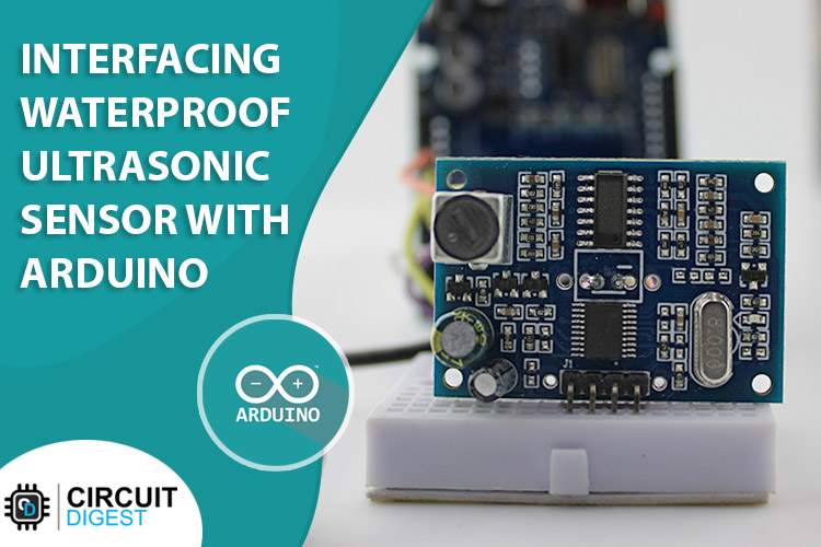
Adding cameras and vision algorithms to your projects and robots might sound cool but sometimes it becomes expensive in terms of both capital and time. When the task at hand is much simpler like obstacle detection, distance measurement, or depth monitoring, ultrasonic sensors are a great alternate to place your bets on. Not only are these sensors fast and accurate but some of their variants like the SR04T and the SR04M also come in waterproof packages making them durable in harsh weather conditions and even underwater applications. This makes them a developer’s first choice as they offer a wide variety of features and easily surpass the more common HC-SR04 sensor in terms of functionality.
The following article shows you how to interface the SR04T Waterproof Ultrasonic sensor with an Arduino Uno to obtain distance data. The article also discusses the working of the module along with a detailed explanation of the code required to process the data into a usable format.
Ultrasonic Sensor Module Pinout
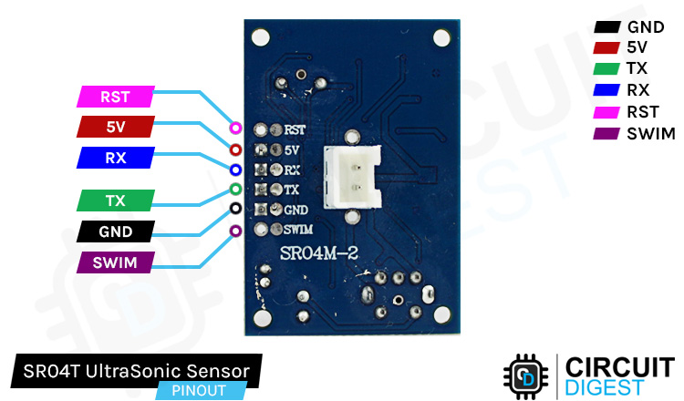
The SR04T/SR04M Module has 6 pins given to the User, RST, 5V, RX, TX, GND, and SWIM. Out of these, 4 are used, and the SWIM and RST are left unused. The functionalities of the pins are :
5V This is the supply input pin of the module. We will provide the 5V supply voltage on this pin.
RX This acts as the Trigger pin for the module. To initiate the sampling of data, we will send a 10us pulse on this pin.
TX This is the Output pin of the module. Post the trigger signal is given to the module, the module sends an output pulse corresponds to the time taken by the waves to bounce back from the obstacle.
GND This is the Ground pin of the module and is used to complete the power supply circuit of the module as well as provide a ground reference to the signals.
SWIM Left Unused
RST Left Unused
How does the Water-proof Ultrasonic Sensor Module Work
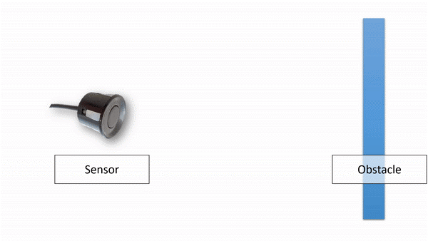
Ultrasonic sensors work by emitting sound waves at a frequency too high for humans to hear. They then wait for the sound to be reflected back, calculating the distance based on the time required. This is similar to how radar measures the time it takes a radio wave to return after hitting an object. A representation of the process can be as follows-
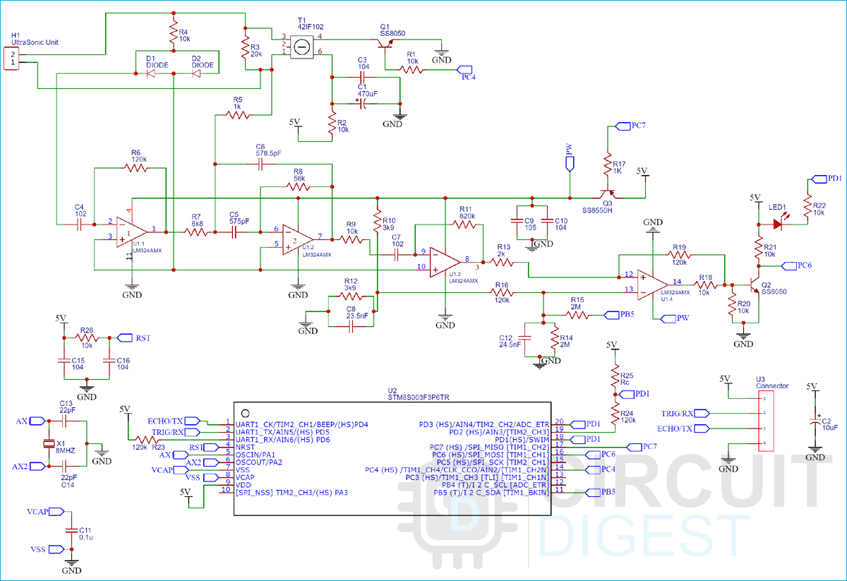
Particularly in the SR04T/SR04M Waterproof Ultrasonic Sensor Modules, the module sends a 40Khz pulse to the ultrasonic unit which then sends the echo back signal to a series of Operational Amplifiers that amplify the receiving signal, this received signal is processed by an on-board STM8 Microcontroller which finally generates an output pulse on the echo pin. The duration of this pulse is the same as the time taken by the sensor to receive the ultrasonic echo.
Using the time taken by the sensor to receive the echo signal as “T”, we can calculate the distance between the sensor and the obstacle by using the formula:
![]()
Ultrasonic Sensor Module Parts
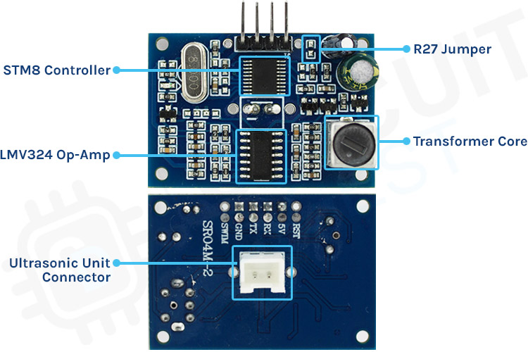
STM8 Controller
This is the main microcontroller present on the module which does all the signal processing as well as controls the mode of operation of the sensor. The controller also generates the 40Khz Frequency pulse needed to operate the ultrasonic sensor unit and then reads the output echo signal back to provide the user with usable data.
LMV324 Op-Amp
The LMV324 Op-Amp IC has 4 stages of Operational Amplifier present on board which is cascaded with each other to process the Echo Signal. Since the received echo signal is often very diminished in nature, we pass it through these 4 stages of Op-Amp and then feed it to the microcontroller for post-processing and calculations on the signal.
Transformer Core
The transformer core is used to tune up the 40Khz Square to a voltage that is operable on the Ultrasonic unit. It is to be fine-tuned by the user to obtain more precise readings.
Ultrasonic Unit Connector
This is a two-pin that is used to connect the module to the ultrasonic unit.
R27 Jumper
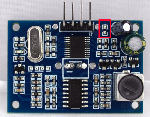
There is a small space present on the PCB that is called the R27 Jumper, by placing different values of resistors on this jumper, we can control the mode of operation of the Ultrasonic Module.
Commonly Asked Questions about the Ultrasonic Sensor Module
Q. Where is the Waterproof Ultrasonic Sensor Used?
Since the sensor provides the user the ability to determine the distance between the sensor and an obstacle, it can be used in applications like:
- The horizontal distance calculation device
- Underwater obstacle avoidance
- Traffic control (Even during harsh weather conditions).
- Water tank level monitoring.
Q. What is the Operating Voltage of the SR04T/SR04M Modules?
The SR04T and SR04M Modules have an Operating Voltage of 5 Volts.
Q. What is the minimum and maximum distance that the ultrasonic module can measure?
The waterproof ultrasonic module can accurately measure a minimum distance of 2.5cm and a maximum distance of 4.5m.
Q. What is the maximum resolution at which the ultrasonic module can provide data?
The waterproof ultrasonic sensor can provide the user with a maximum resolution of 0.5cm.
Waterproof Ultrasonic Sensor Module Circuit Diagram
Operating Modes of SR04T/SR04M Ultrasonic Module
The Ultrasonic module works in 5 different modes. Using the R27 jumper present on the module PCB, we can control the operating mode of the Module.
The different modes of operation are:
Mode 1: Standard Trigger Mode (R27 Kept Open)

The Module works like other widely used SR04 modules where a pulse of 10us has to be provided to obtain output on the echo pin. The standby current is <2.5mA and the working current is 30mA.
Mode 2: Low Power Trigger Mode (R27 as a 300kΩ Resistor)
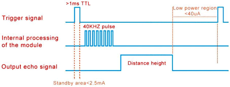
This mode is similar to Mode 1 (Standard Trigger Mode), the only difference is that the Trigger pulse must be of a width greater than 1ms. In the following mode, the standby current is very low <40uA hence conserving power.
Mode 3: Serial Port Automatic Mode (R27 as a 120kΩ Resistor)

In this mode the data is sent in the form of a Serial packet, The trigger line has no effect on the module, the module automatically sends pulses after an interval of 120ms and sends the time data to the user on the ECHO output line in the form of a Serial Packet. The average power consumption in this mode is 5mA.
Mode 4: Serial Low Power Mode (R27 as a 47kΩ Resistor)
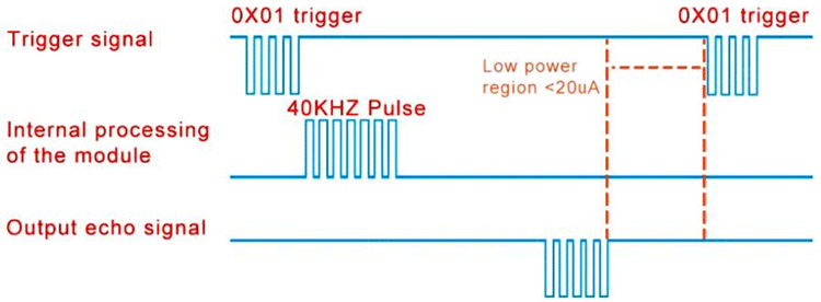
This mode can be said a combination of the Standard Mode (Mode1) and the Serial Automatic Mode (Mode 3). In this mode, we first send a Serial Data Packet on the TRIGGER Line. This data packet (0X01) wakes the module and the module sends a pulse internally to obtain the output, the output is then sent to the user in the form of a Serial Packet on the output ECHO line. Post this, the module enters the low power mode consuming as low as 20uA.
Mode 5: Computer Printing Mode (R27 kept as a short)
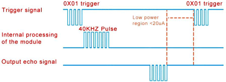
This mode is similar to the Serial Low Power Mode i.e., Mode 4 of the module. A serial command (0X01) is sent to the module on the TRIG pin, and the module sends a pulse internally to obtain the echo time. In this mode, the module automatically calculates the distance in mm and outputs an ASCII-coded serial packet on the ECHO Pin. This makes the module directly usable on any serial terminal.
Note: We would use the default mode, Mode 1. That is the Standard Trigger Mode to avoid soldering and rework on our module.
Timing Diagram
To obtain a reading from the sensor, we first provide the sensor with an input pulse of 10uS on the Trigger pin.
Once the sensor receives the trigger input, it sends 8 bursts of 4KHz to the Ultrasonic Unit.
The echo of this burst is processed by the sensor and on the Echo pin, a pulse is generated that is of the same duration as the time taken by the signal to echo off the obstacle.
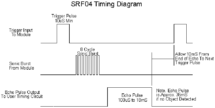
We read the duration of this echo pulse and calculate the distance between the sensor and the obstacle by multiplying it with the speed of sound.
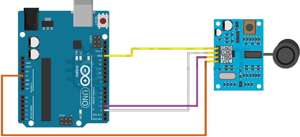
Ultrasonic Module with Arduino Connection Diagram
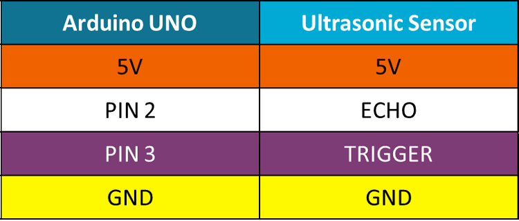
The Following connections are made between Arduino UNO and the Sensor:
Arduino Code
As discussed in the working section, we need to send 10uS pulses on the TRIGGER pin and measure the duration of the pulse received on the ECHO Pin.
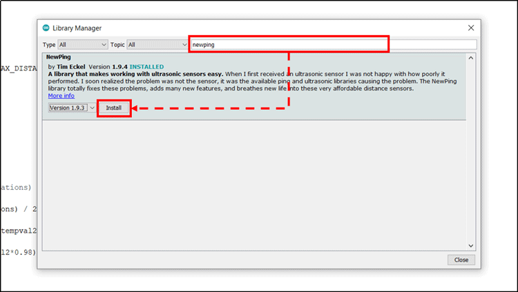
To achieve this functionality, we simply use the “NewPing” library that can be installed using the library manager as follows.
Installing The Required Library:
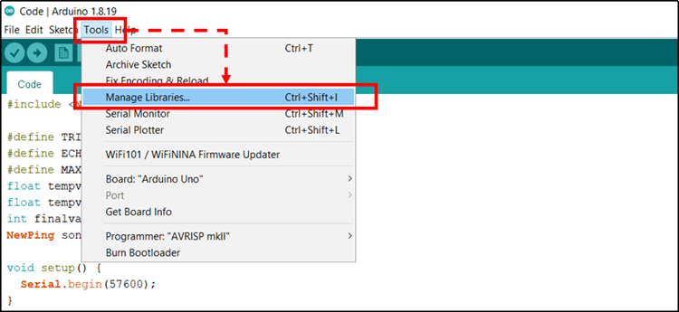
1. Open the Tools Menu on the menu bar and select the library manager.
2. Once the Library Manager is open, in the search bar, Search for “NewPing” library and click on install to install the latest version of the library.
Using the NewPing Library
To use the NewPing library, we will initialize the pins as per our connections and initialize a NewPing Object.
Along with this, we also initialize variables to store the values read from the sensor. Notice that we have initialized three variables, this will be explained further when we look into the raw data processing.
#include <NewPing.h>
#define TRIGGER_PIN  3
#define ECHO_PIN     2
#define MAX_DISTANCE 400
NewPing sonar(TRIGGER_PIN, ECHO_PIN, MAX_DISTANCE);
float tempval1;
float tempval2;
int finalval;
Setup Function
In the Void Setup() function, we simply initialize the serial port at a baud rate of 57600.
void setup() {
  Serial.begin(57600);
}
Loop Function
void loop() {
  delay(20);
  Serial.print("Ping: ");
  int iterations = 5;
  tempval1=((sonar.ping_median(iterations) / 2) * 0.0343);
  if(tempval1-tempval2>60 || tempval1-tempval2<-60)
  {
    tempval2=(tempval1*0.02 )+ (tempval2*0.98);
    }
  else
  {
  tempval2=(tempval1*0.4 )+ (tempval2*0.6);
  }
  finalval=tempval2;
  Serial.print(finalval);
  Serial.println("cm");
}
- This function contains the most crucial part of the code.
- We use the “sonar.ping_median()” function to take 5 iterations of values and then find the median of those values, this gives us a more accurate and reliable value.
- The function provides us with the time value, to obtain the distance, we simply multiply it by 0.0343 (speed of sound in cm/us) and then take a half to obtain the distance between the sensor and the obstacle.
- This value is though stored in a temporary variable “Tempval1”. Our usable value is stored in “Tempval2”.
- While updating the values, if the difference between Tempval1 and Tempval2 is large (>60 OR <-60), we give less weightage to the new sensor reading in calculating Tempval2.
- If this difference is small, we calculate Tempval2 by adding 40% of the new sensor data (Tempval1) with 60% of the old reading (Tempval2);
- This smoothens out the fluctuations that might occur in the sensor due to noise.
- In the end, we cast the float variable Tempval2 to an integer variable “Finalval” and display it to the user on the serial using the Serial.print command.
Output
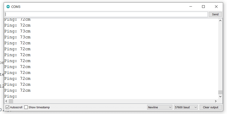
Once the code is compiled and uploaded on the Arduino, open the Serial monitor to view the output of the system.
Note:
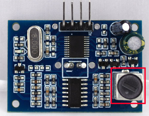
If the system does not give correct output or gives erratic readings, adjust the transformer present on the top left corner of the board as shown in the diagram.
Working of the Ultrasonic Sensor Module
Supporting Files
#include <NewPing.h>
#define TRIGGER_PIN  3
#define ECHO_PIN     2
#define MAX_DISTANCE 400
NewPing sonar(TRIGGER_PIN, ECHO_PIN, MAX_DISTANCE);
float tempval1;
float tempval2;
int finalval;
void setup() {
  Serial.begin(57600);
}
void loop() {
  delay(20);
  Serial.print("Ping: ");
  int iterations = 10;
  tempval1=((sonar.ping_median(iterations) / 2) * 0.0343);
  if(tempval1-tempval2>60 || tempval1-tempval2<-60)
  {
    tempval2=(tempval1*0.02 )+ (tempval2*0.98);
    }
  else
  {
  tempval2=(tempval1*0.4 )+ (tempval2*0.6);
  }
  finalval=tempval2;
  Serial.print(finalval);
  Serial.println("cm");
}

