Starting with physical switches, the way we interact with electronic devices has evolved significantly over the years. We moved from switches to touch screens, and research has continued to push the boundaries further. Today, we've gesture recognition, where you can control and access machines without any physical touch. While it may seem hyped, experiencing gesture recognition buy building one yourself is really fun!
In exploring gesture recognition, we chose the PAJ7620 Gesture Recognition Module. This module stands out because it comes with nine pre-programmed gesture recognitions. Many other gesture sensors on the market either recognize fewer gestures or only provide raw data, making them challenging to interface with. The PAJ7620 simplifies this process, making it an ideal choice for our exploration. If you want to know want kind of Arduino projects you can build using gesture sensors you can check out gesture controlled robotic arm and gesture controlled arduino car projects, both of which were build by us here in circuitdigest sometime back
PAJ7620 Gesture Recognition Sensor
The PAJ7620 Gesture Sensor is a versatile and user-friendly module ideal for electronics hobbyists. At the heart of this module is the PAC720 chip, which integrates gesture recognition capabilities with a general I2C interface, creating a comprehensive image analytic sensor system. This advanced module can recognize a variety of human hand gestures, making it highly useful for interactive applications.
Specifically, it can detect nine different gestures: moving up, down, left, right, forward, backward, clockwise, anti-clockwise, and waving. These capabilities allow for a wide range of applications, from simple project enhancements to complex interactive systems. The ease of use and broad functionality make the PAJ7620 Gesture Sensor a valuable addition to any electronics toolkit.
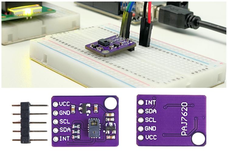
In the above image, you can see the front and back sides of the PAJ7620 Gesture Recognition Module. It's a small, simple-to-understand module in every aspect. To get more familiar with this module, let's know the specifications briefly!
PAJ7620 Gesture Recognition Module Specification
Still, now we are saying PAJ7620, but actually, the full name is PAJ7620U2. This is important to know if you think about utilizing all features of this integrated circuit. Let's take a quick look at the specifications of this module.
| Parameter | Symbol | Limits | Limits | Limits | Unit |
| Min | Typical | Max | |||
| Supply Voltage | Vcc | 3.3 | 5 | 6 | V |
| IO Pin Voltage | Vio | 1.8 | - | 3.3 | v |
| Supply Current | Ic | - | 370 | 800 | mA |
| Gesture Detection Range | Dop | 5 | - | 15 | cm |
| Operating Temperature | Top | -40 | - | 85 | °C |
| Storage Temperature | Tstorage | -40 | - | 125 | °C |
Above, you can see the small table mentioning the specifications. This module is compatible with every microcontroller that has I2C hardware support. The only thing to remember is the IO pin voltage level. This module only accepts voltage up to 3.3V. If you are using a 5V microcontroller or something above that, I suggest using a logic level shifter between the data lines. Also, there are many level-shifting modules available in the market, which you can check out on the internet.
Another cool thing to notice is that it has a quite long sensing range, which is around 20 cm, but the most accurate range mentioned by the manufacturer is around 15 cm. Next, let's get a bit technical by looking at the pinouts.
PAJ7620 Gesture Recognition Module Pinouts
As this is a module, there is not much complexity. There are only 5 pins, which are really easy to understand. You can see the exact image of the PAJ7620 Module with the appropriate pinouts mentioned.
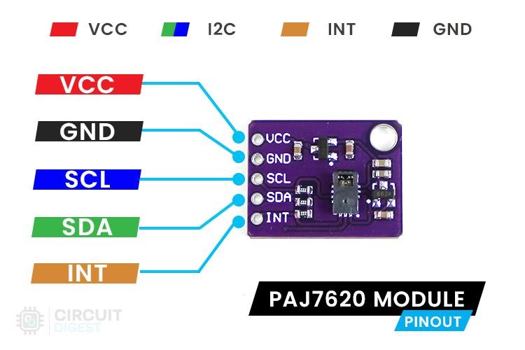
Below is the table that consists of the pin description of this PAJ7620 module. Everything here is quite simple; none of it involves complex terms or has complex functionality.
| Pin No | Pin Name | Description |
| 1 | VCC | Positive Voltage Input Pin |
| 2 | GND | Ground Voltage Input Pin |
| 3 | SCL | I2C Serial Clock Pin |
| 4 | SDA | I2C Serial Data Pin |
| 5 | INT | Interrupt pin |
Starting with Vcc, it is the input voltage pin, which supports up to 6V due to its internal linear voltage regulators. Still, 5V is recommended for optimal long-term performance. Next come the SCL and SDA pins, which are I2C communication pins. A fun fact about it is that the PAJ7620 also supports SPI communication, but those pins are not extracted in this module. So, if you prefer to use SPI, check for other possible modules or make your own PCB. Simple!
Next comes the Interrupt Pin. I found that it is responsible for indicating if any gesture is recognized. It is usually high, and in case any gesture is detected, it becomes low, which is very handy in terms of coding. You can read the data from the register only after reading this signal, which reduces the occurrence of false queries to the PAJ7620 IC.
The above GIFs explain the phenomenon of the interrupt pin, as described above. You can see that the low signal is available only for a short time because in our code, we already fetched the Recognised gesture code, so the interrupt flag was cleared.
PAJ7620 Gesture Recognition Module’s Schematic Explanation
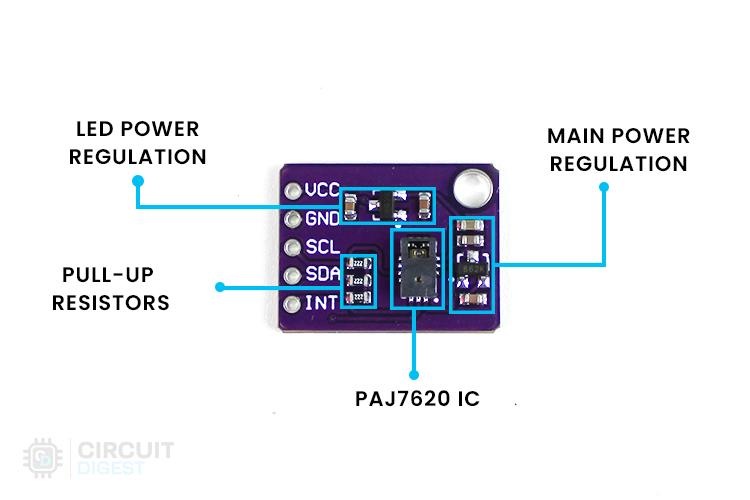
Below you can see the actual image of the PAJ7620 IC with its main blocks marked. So yes, there are four main sections that need to be discussed: PAJ7620 IC Connection itself, Main Power Regulation Circuit, LED Power Regulation Circuit, and Pull-up Resistor Network.
Here we are going to discuss the schematic of the PAJ7620 Module, starting from the Power Section.
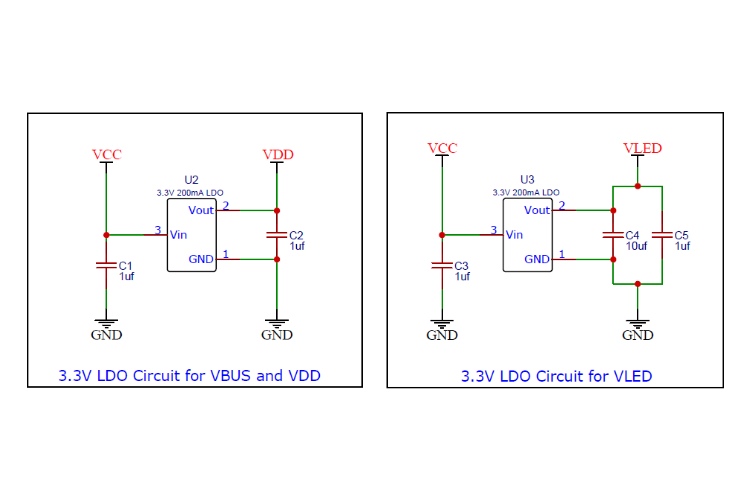
Above, you can see the power section, which is responsible for powering individual components of the PAJ7620. As you know, three separate sections are present which need three separate voltages: VBUS (1.8V - 3.3V), VDD (2.8V - 3.6V), and VLED (3.0V - 4.2V). VDD is the main power supply, and VBUS is the bus power supply. Both of these have a common LDO which provides a 3.3V linear output because of their low power consumption. VLED is powered by another separate LDO, which is also a 3.3V output linear regulator.
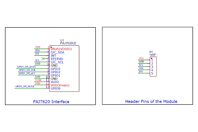
The image you can see above shows the PAJ7620 connections. You might understand it easily as it is quite straightforward. No extra components are needed here. Those power supplies were directly connected to the respective pins of the IC. One thing you need to know is that the SPI pins are held as no connection pins; they were not extracted out. Otherwise, they have a connection with the main header pins.
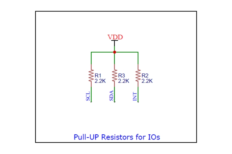
At last, you can see pull-up resistors connected to the IOs of the PAJ7620 to provide a stable logic state for the pins. Therefore, I wish to say that I covered the schematic of the module which I have on my desk. There are lots of modules available out there which might have a different approach towards the PAJ7620.
Okay, now, seeing all these theories, you might get bored, so let's quickly move towards the practical thing.
How does this PAJ7620 Gesture Recognition Module Work?
Dividing this into two parts, first let's look at the internal, and next, we'll move to external.
Internal Working of PAJ7620
The internal working is not the most confusing thing. It is just a camera that does this magic. Internally, there is a 60x60 Pixel Camera along with an IR LED and an integrated processing unit. So, yes, the movements are captured via the camera and passed to the object extraction and gesture recognition unit, and the recognized gesture is stored in the register bank and read via the I2C hardware pins.
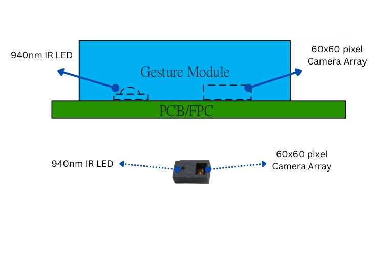
Above, you can see the internal illustration of the PAJ7620 Sensor. If you would like to protect the sensor from the external environment, kindly refer to the official paj7620 datasheet for the procedures.
External Working of PAJ7620
External working is most straightforward. Within its range of 5 to 15 cm with a viewing angle of 60 degrees, if we show any of the following gestures, it is recognized, and we can get the result instantly via I2C.
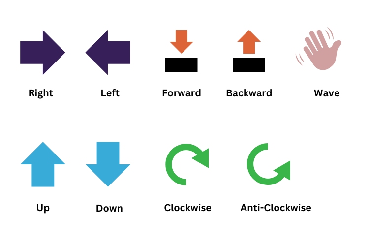
Above, you can see the hand gesture signs that can be recognized by the module. Let me reveal some features here: you can even detect more gestures, literally more than 9, just by combining the primary gestures. And it has limitations; we can do such functionality in normal mode. If you prefer to use the faster frame rate, which is known as Gaming mode, you can do that. To learn more about these experiments, you can use this link which redirects you to DFRobot_PAJ7620U2. It has example programs which apply the concept I explained above.
So, thereby, we've completed the working of the PAJ7620 Sensor. Next, let's delve into the actual hardware.
Circuit Diagram for Interfacing PAJ7620 Gesture Sensor Module with Arduino UNO
For easy understanding of the output, I am using an LCD display with I2C provision. So, don’t limit your imagination to this concept; there are a lot of things you can do with this. You can visit the following link to get more ideas about using this gesture recognition module.

Above, you can see the interfacing circuit diagram. You might wonder that I used some unnamed pins of the Arduino UNO. Don’t be confused; those pins are usable. I have followed a color code for this whole article, like RED for 5V or positive power supply, BLACK for ground or negative power supply, GREEN for serial data (SDA) pin of I2C communication, and BLUE for serial clock (SCL) pin of I2C communication. With this, you can easily understand the above image.
You might notice I used resistors to connect Arduino Data Pins with the PAJ7620. Yes, it has a purpose. The actual maximum threshold voltage of the IO pins of PAJ7620 can handle is 3.3V. So, as we are going to interface PAJ7620 with this 5V microcontroller, the resistor is used to limit the current in the data lines. It's not a perfect solution, but as a hobby project, this trick comes in handy. If you are looking to use this module permanently in a product, I suggest using a bidirectional level shifter module available in the market.
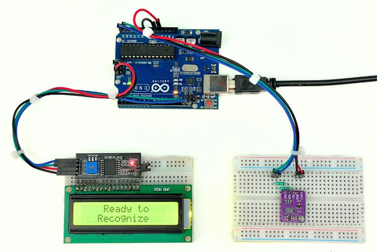
Above, you can see the assembled image of the PAJ7620 Gesture Recognition Module interfacing with Arduino UNO, but more than just assembled, it's also programmed. So, hold your curiosity; let's get into coding!
Code for Interfacing PAJ7620 Gesture Recognition Module with Arduino UNO
As we are in the age of Arduino, we don't need to worry about interfacing this PAJ7620 Sensor with Arduino. We have numerous pre-written libraries. Among them, I selected a library made by DFRobot, which is DFRobot_PAJ7620U2. You can install the paj7620 library by cloning it directly into your Arduino’s Library Folder, or below is a shortcut.
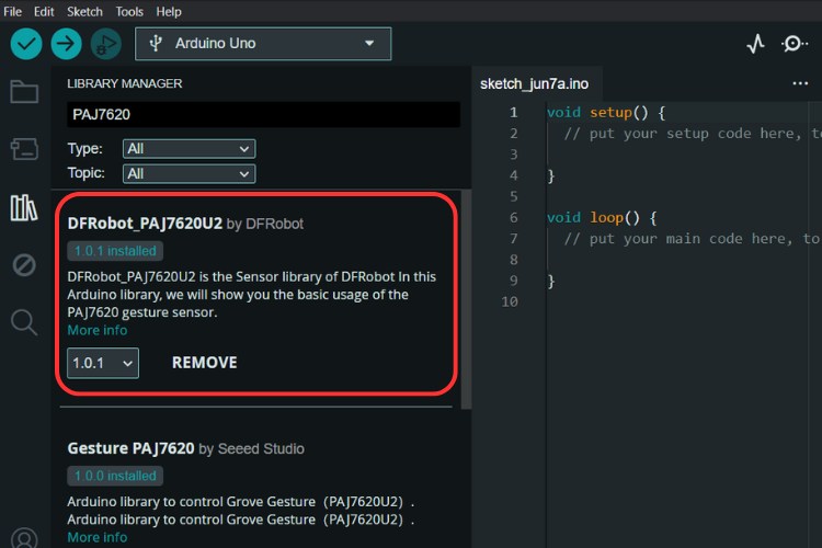
Like above, we can search in the library manager of the Arduino IDE by simply typing PAJ7620 in its search box. It's that simple.
If you'd like to explore the example program, you can; it's really awesome. But in this article, let’s look at the modified code. Since we are also adding an LCD, let's add that library as well. You can add it via this link: Arduino-LiquidCrystal-I2C-library. Let’s go to the code explanation.
#include <DFRobot_PAJ7620U2.h>
#include <Wire.h>
#include <LiquidCrystal_I2C.h>
The above three libraries are added initially.
uint8_t rightChar[8] = { B00000, B00000, B00100, B00010, B11111, B00010, B00100, B00000 };
uint8_t leftChar[8] = { B00000, B00000, B00100, B01000, B11111, B01000, B00100, B00000 };
uint8_t upChar[8] = { B00000, B00000, B00100, B01110, B10101, B00100, B00100, B00000 };
uint8_t downChar[8] = { B00000, B00100, B00100, B10101, B01110, B00100, B00000, B00000 };
uint8_t forwardChar[8] = { B00100, B10101, B01110, B00100, B00000, B00000, B01110, B01110 };
uint8_t backwardChar[8] = { B00100, B01110, B10101, B00100, B00000, B00000, B01110, B01110 };
uint8_t clockwiseChar[8] = { B01110, B10001, B00001, B00001, B01010, B01100, B01110, B00000 };
uint8_t antiClockwiseChar[8] = { B00000, B01110, B01100, B01010, B00001, B00001, B10001, B01110 };
uint8_t waveRightChar[8] = { B00111, B00011, B00101, B01000, B00010, B10100, B11000, B11100 };
uint8_t waveLeftChar[8] = { B11100, B11000, B10100, B00010, B01000, B00101, B00011, B00111 };
To make the visualization pretty good, I am adding some custom characters. Note that you can use only 8 custom characters at a time.
void setup() {
  Serial.begin(115200);
  delay(300);

  lcd.begin();
  lcd.createChar(1, waveRightChar);
  lcd.createChar(2, waveLeftChar);
  lcd.createChar(3, upChar);
  lcd.createChar(4, downChar);
  lcd.createChar(5, forwardChar);
  lcd.createChar(6, backwardChar);
  lcd.createChar(7, clockwiseChar);
  lcd.createChar(8, antiClockwiseChar);

  Serial.println("Gesture recognition system base on PAJ7620U2");
  while (paj.begin() != 0) {
    Serial.println("initial PAJ7620U2 failure! Please check if all the connections are fine, or if the wire sequence is correct?");
    delay(500);
  }
  Serial.println("PAJ7620U2init completed, start to test the gesture recognition function");

  paj.setGestureHighRate(false);
}
Next comes the `void setup` function. Here, as we are going to interface two I2C hardware components, we need to ensure the proper connection. So first, we initialize both libraries using their objects, starting with `lcd.begin();`.
  Serial.println("Gesture recognition system base on PAJ7620U2");
  while (paj.begin() != 0) {
    Serial.println("initial PAJ7620U2 failure! Please check if all the connections are fine, or if the wire sequence is correct?");
    delay(500);
  }
  Serial.println("PAJ7620U2init completed, start to test the gesture recognition function");
Next, `paj.begin();` is used to ensure the proper connection between the PAJ7620 and Arduino Uno. Once this function returns `true`, the `while` loop is exited and the next functions are executed.
paj.setGestureHighRate(false);
If the above is set to true, you have enabled a higher reading rate, also known as gaming mode. One thing to note is that if you are using gaming mode, you can use the pre-embedded 9 gesture signs, but not the additional four extended gestures.
void loop() {

  DFRobot_PAJ7620U2::eGesture_t gesture = paj.getGesture();
  if (gesture != paj.eGestureNone) {
    lcd.clear();

    String description = paj.gestureDescription(gesture);
    Serial.println("--------------Gesture Recognition System---------------------------");
    Serial.print("gesture code        = ");
    Serial.println(gesture);
    Serial.print("gesture description  = ");
    Serial.println(description);
    Serial.println();

    switch (gesture) {
      case 1:
        lcd.setCursor(3, 0);
        lcd.write(byte(1));
        lcd.print(" ");
        lcd.print("RIGHT");
        lcd.print(" ");
        lcd.write(byte(1));
        break;
     // … program for other conditions are used
      default:
        lcd.print("New Gesture");
        break;
    }
  }
}
The above is the `void loop` part of the program. Here, the `paj.getGesture()` function is used to get the hex code of the last recognized gesture from the register bank of PAJ7620 via I2C. If the received data is 0, no gesture is read; otherwise, in the case of any value, we can assume that some gesture is recognized. It is then compared with the prewritten variables in the PAJ7620 library, which you can see below.
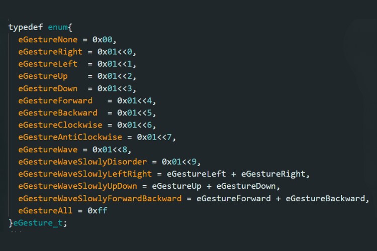
For reducing confusion, I converted the hexadecimals to decimals. Here they are:
- None = 0
- Right = 1
- Left = 2
- Up = 4
- Down = 8
- Forward = 16
- Backward = 32
- Clockwise = 64
- AntiClockwise = 128
- Wave = 256
- WaveSlowlyDisorder = 512
- WaveSlowlyLeftRight = 3
- WaveSlowlyUpDown = 12
- WaveSlowlyForwardBackward = 48
- All = 255
Next, these values received are passed to a switch case to perform the respective function. In our case, we change the display characters as per the received recognized gesture code. That's it; coding part completed. You can find the full code below. Next, let’s see the working demo.
Working Demonstration of Interfacing PAJ7620 Gesture Recognition Module with Arduino UNO
After uploading the code to the Arduino, our project is ready for recognizing gestures and displaying them on the screen. No surprise, below you can see the GIFs of the working demo of the basic recognizable gestures, which are: Right, Left, Up, Down, Forward, Reverse, Clockwise, Anti-Clockwise, and Wave.
Now you can see the extended gestures, which are: Wave Slowly Disorder, Wave Slowly Left-Right, Wave Slowly Up-Down, and Wave Slowly Forward-Backward, in the below GIFs.
Here, the working is simple. As I set the PAJ7620 at a low sample rate, I managed to get 13 types of gestures to be recognized. As I mentioned before, if you need high-speed sampling, you can get only 9 gestures, which might be enough in some cases.
Here’s the GitHub repo where you can find the complete code and the circuit diagrams used in this article.

#include <DFRobot_PAJ7620U2.h>
#include <Wire.h>
#include <LiquidCrystal_I2C.h>
// Set the LCD address to 0x27 for a 16 chars and 2 line display
LiquidCrystal_I2C lcd(0x27, 16, 2);
uint8_t rightChar[8] = { B00000, B00000, B00100, B00010, B11111, B00010, B00100, B00000 };
uint8_t leftChar[8] = { B00000, B00000, B00100, B01000, B11111, B01000, B00100, B00000 };
uint8_t upChar[8] = { B00000, B00000, B00100, B01110, B10101, B00100, B00100, B00000 };
uint8_t downChar[8] = { B00000, B00100, B00100, B10101, B01110, B00100, B00000, B00000 };
uint8_t forwardChar[8] = { B00100, B10101, B01110, B00100, B00000, B00000, B01110, B01110 };
uint8_t backwardChar[8] = { B00100, B01110, B10101, B00100, B00000, B00000, B01110, B01110 };
uint8_t clockwiseChar[8] = { B01110, B10001, B00001, B00001, B01010, B01100, B01110, B00000 };
uint8_t antiClockwiseChar[8] = { B00000, B01110, B01100, B01010, B00001, B00001, B10001, B01110 };
uint8_t waveRightChar[8] = { B00111, B00011, B00101, B01000, B00010, B10100, B11000, B11100 };
uint8_t waveLeftChar[8] = { B11100, B11000, B10100, B00010, B01000, B00101, B00011, B00111 };
DFRobot_PAJ7620U2 paj;
void setup() {
Serial.begin(115200);
delay(300);
lcd.begin();
lcd.createChar(1, waveRightChar);
lcd.createChar(2, waveLeftChar);
lcd.createChar(3, upChar);
lcd.createChar(4, downChar);
lcd.createChar(5, forwardChar);
lcd.createChar(6, backwardChar);
lcd.createChar(7, clockwiseChar);
lcd.createChar(8, antiClockwiseChar);
Serial.println("Gesture recognition system base on PAJ7620U2");
while (paj.begin() != 0) {
Serial.println("initial PAJ7620U2 failure! Please check if all the connections are fine, or if the wire sequence is correct?");
delay(500);
}
Serial.println("PAJ7620U2init completed, start to test the gesture recognition function");
paj.setGestureHighRate(false);
lcd.backlight();
lcd.setCursor(4, 0);
lcd.print("Ready to");
lcd.setCursor(3, 1);
lcd.print("Recognize");
}
void loop() {
DFRobot_PAJ7620U2::eGesture_t gesture = paj.getGesture();
if (gesture != paj.eGestureNone) {
lcd.clear();
String description = paj.gestureDescription(gesture);
Serial.println("--------------Gesture Recognition System---------------------------");
Serial.print("gesture code = ");
Serial.println(gesture);
Serial.print("gesture description = ");
Serial.println(description);
Serial.println();
switch (gesture) {
case 1:
lcd.setCursor(3, 0);
lcd.write(byte(1));
lcd.print(" ");
lcd.print("RIGHT");
lcd.print(" ");
lcd.write(byte(1));
break;
case 2:
lcd.setCursor(4, 0);
lcd.write(byte(2));
lcd.print(" ");
lcd.print("LEFT");
lcd.print(" ");
lcd.write(byte(2));
break;
case 4:
lcd.setCursor(5, 0);
lcd.write(byte(3));
lcd.print(" ");
lcd.print("UP");
lcd.print(" ");
lcd.write(byte(3));
break;
case 8:
lcd.setCursor(4, 0);
lcd.write(byte(4));
lcd.print(" ");
lcd.print("DOWN");
lcd.print(" ");
lcd.write(byte(4));
break;
case 16:
lcd.setCursor(2, 0);
lcd.write(byte(5));
lcd.print(" ");
lcd.print("FORWARD");
lcd.print(" ");
lcd.write(byte(5));
break;
case 32:
lcd.setCursor(2, 0);
lcd.write(byte(6));
lcd.print(" ");
lcd.print("BACKWARD");
lcd.print(" ");
lcd.write(byte(6));
break;
case 64:
lcd.setCursor(2, 0);
lcd.write(byte(7));
lcd.print(" ");
lcd.print("CLOCKWISE");
lcd.print(" ");
lcd.write(byte(7));
break;
case 128:
lcd.setCursor(4, 0);
lcd.write(byte(8));
lcd.print(" ");
lcd.print(" ");
lcd.print(" ");
lcd.write(byte(8));
lcd.setCursor(1, 1);
lcd.print("ANTI-CLOCKWISE");
break;
case 256:
lcd.setCursor(4, 0);
lcd.write(byte(2));
lcd.print(" ");
lcd.print("WAVE");
lcd.print(" ");
lcd.write(byte(1));
break;
case 512:
lcd.setCursor(2, 0);
lcd.write(byte(2));
lcd.print(" ");
lcd.print("SLOW WAVE");
lcd.print(" ");
lcd.write(byte(1));
lcd.setCursor(4, 1);
lcd.print("DISORDER");
break;
case 3:
lcd.setCursor(2, 0);
lcd.write(byte(2));
lcd.print(" ");
lcd.print("SLOW WAVE");
lcd.print(" ");
lcd.write(byte(1));
lcd.setCursor(3, 1);
lcd.print("LEFT-RIGHT");
break;
case 12:
lcd.setCursor(2, 0);
lcd.write(byte(2));
lcd.print(" ");
lcd.print("SLOW WAVE");
lcd.print(" ");
lcd.write(byte(1));
lcd.setCursor(4, 1);
lcd.print("UP-DOWN");
break;
case 48:
lcd.setCursor(2, 0);
lcd.write(byte(2));
lcd.print(" ");
lcd.print("SLOW WAVE");
lcd.print(" ");
lcd.write(byte(1));
lcd.setCursor(1, 1);
lcd.print("FORWARD-BACKWARD");
break;
default:
lcd.print("New Gesture");
break;
}
}
}