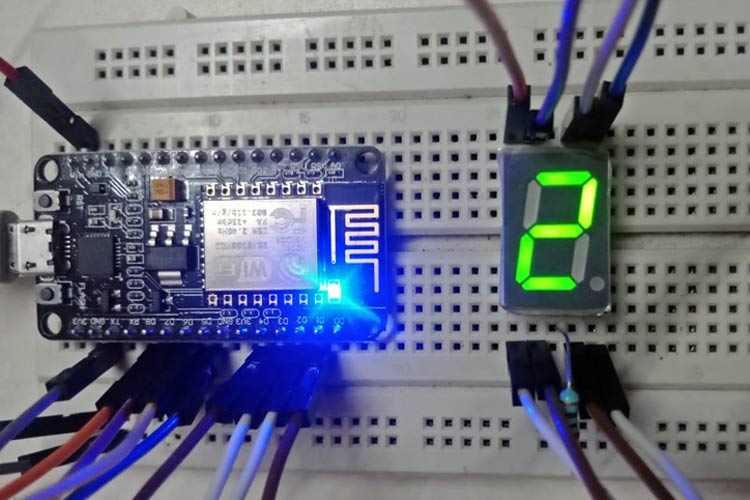
Any electronics projects enthusiast has to first familiarize themselves with basic electronic projects. This includes trying to build simple devices and circuits using components like resistors, LEDs, diodes, transistors, etc. This forms a firm foundation in handling electronic components and helps to build complex projects later. Once familiar with the basics, one can move on to sensors and actuators. Using them is a lot easier with development boards like Arduino, NodeMCU, or Raspberry Pi work on a bit complex electronic projects. Here, we have described a beginner level project with NodeMCU. An ESP8266 is programmed to display ‘0’ to ‘9’ and ‘a’ to ‘f’ on the Seven Segment Display. You can check out other esp8266 Projects on our website.
Introduction to NodeMCU – ESP8266
NodeMCU is basically a low-cost, open-source hardware and software development platform for hobbyists to build projects. It has a growing community and has a great fan base. To put it in simple terms, NodeMCU is an open-source firmware developed for the ESP8266 Wi-Fi chip. ESP8266 is a Wi-Fi system on a chip produced by Espressif Systems. ESP8266 can serve as a Wi-Fi-enabled microcontroller or can be used as an external Wi-Fi module. Standard AT commands are be used when ESP8266 is used as an external Wi-Fi module and it communicates with the microcontroller using serial UART. Or if it is serving as a Wi-Fi-enabled microcontroller by programming using the provided SDK.
Learning about Seven Segment Displays
Seven Segment Display (SSD) is a commonly used output device that can display digits and letters. It’s mostly used in calculators, digital watches, etc. It is basically 7 LED segments arranged like an “8” for ease of display. Each segment is connected to a pin and is called ‘a’, ‘b’, ‘c’, ‘d’, ‘e’, and ‘f’ pins. Along with this, it has a dot which is called a ‘dp’ pin.
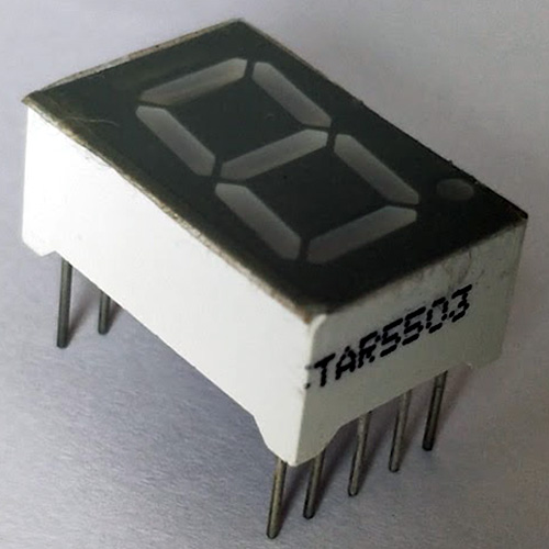
The figure shows physical appearance of the Seven Segment Display
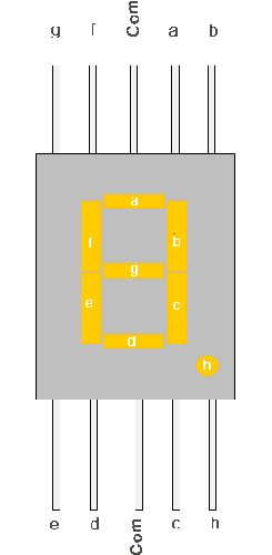
The figure shows the pinout of Seven Segment Display
The SSD is of two types: Common Cathode and Common Anode. In the common cathode, all the cathode pins of LED segments are connected and given as “Common pin” of the SSD. This pin is connected to the ground so that when a positive voltage is given to any segment, that completes the circuit and that segment is lit. Similarly, in a common Anode, all the positive terminals (anode terminals) of LED segments are shorted and given as “Common pin” of SSD, and this pin is connected to positive voltage.
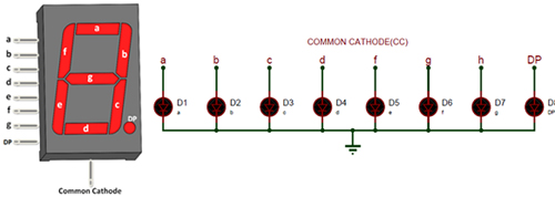
The figure here shows Common Cathode type SSD
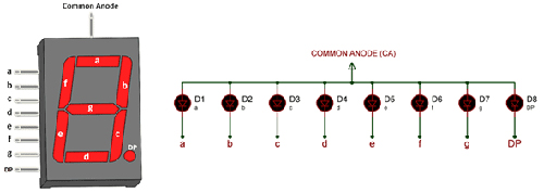
The figure of Common Anode type SSD
Components Required to Interface ESP8266 with Seven Segment Display
- ESP8266 development board
- Seven Segment Display (Common Cathode is used here)
- 100-ohm resistor
- Breadboard
- Jumper cables
Circuit Diagram to Interface a Seven-Segment Display with NodeMCU
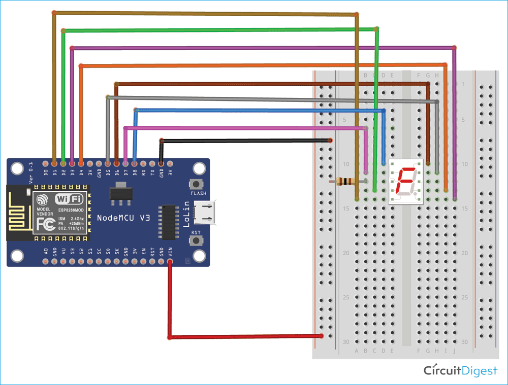
Since this is a beginner-level project, the circuit is very simple as you can see in the figure given below.
Connect the GND pin of ESP8266 to the negative rail of the breadboard and the Vin pin of ESP8266 to the positive rail of the breadboard. Connect D8, D7, D6, D5, D4, D3, D2, and D1 of ESP8266 pins to ‘g’, ‘f’, ‘a’, ‘b’, ‘c’, ‘dp’, ‘e’ and ‘d’ pin of SSD respectively. Connect one of the common pin of SSD to negative rail through a 100-ohm resistor (to limit the current so it doesn’t damage the SSD).
Powering NodeMCU and SSD
The ESP8266 is powered when it is connected to the computer or laptop through the MicroB USB connector. A 3.3V output supply generated by the on-board regulator. This is used to supply power to the SSD through the ‘Vin’ pin.
Coding ESP8266 to Control Seven Segment Display
A simple code is written on Arduino IDE to control the segments of the SSD to display the required digit or the alphabet. The GPIO pins of ESP8266 are connected to the pins of SSD to control that segment. Whenever we want a particular segment to be lit, we supply a positive voltage to it. The complete code can be found at the end of the page. Make sure to install the “ESP8266” library before proceeding to code. This part is explained in the video in detail.
Open the Arduino IDE and declare the pins of SSD (A, B, C, etc) as “const”, “int” type data and assign them to GPIO pins of ESP8266. In the “void setup()” function, declare the pins of SSD as “OUTPUT”. Whatever is written inside the “void setup()” function is executed only once. This part is necessary to light up particular segments so that multiple lit segments make up a number or alphabet, as explained.
For example:
const int A = 12;
const int B = 14;
void setup() {
  pinMode(A, OUTPUT);
  pinMode(B, OUTPUT);
  .
  .
  .
}
In the “void loop()” function, call different functions to be displayed along with a delay of one second. The delay of one second is achieved by “delay(1000);” This is necessary because, without a proper amount of delay, it’s hard for the human eye to see what is displayed.
Example:
zero();
delay(1000);
one();
delay(1000);
Next, declare which all segments of SSD to be HIGH and which all to be LOW by using the “digitalWrite” function. Refer to the pinout diagram for this section; based on that, we can conclude which all segments to declare as “HIGH” and which all as “LOW” so we can display the alphanumeric character we want.
For example:
void zero(){
  digitalWrite(A, HIGH);
  digitalWrite(B, HIGH);
  digitalWrite(C, HIGH);
  digitalWrite(D, HIGH);
  digitalWrite(E, HIGH);
  digitalWrite(F, HIGH);
  digitalWrite(G, LOW);
  digitalWrite(DP, LOW);
}
Observation on pins of ESP8266
Initially in the code A is assigned to 12, B is assigned to 14, etc. This is because the pins D6, D5, etc are nothing but GPIO (General Purpose Input Output) pins of NodeMCU. D8 is nothing but GPIO15, D7 is GPIO13, D6 is GPIO12, etc.
Debugging the Connections of NodeMCU to SSD
If your code is not properly uploaded in NodeMCU, try to unplug the D8 of NodeMCU while uploading the code. And reconnect this pin after uploading. You need not make any changes to the code while doing this.
Working of Seven Segment Display with NodeMCU for the code written
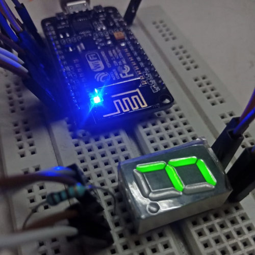
After making the circuit connections and uploading the code (you can see the onboard LED blinking periodically), the Seven Segment Display should start displaying numbers from “0” to “9” and start displaying alphabets from “A” to “F” after “F” it loops back to “0” and this continues till the power is disconnected.
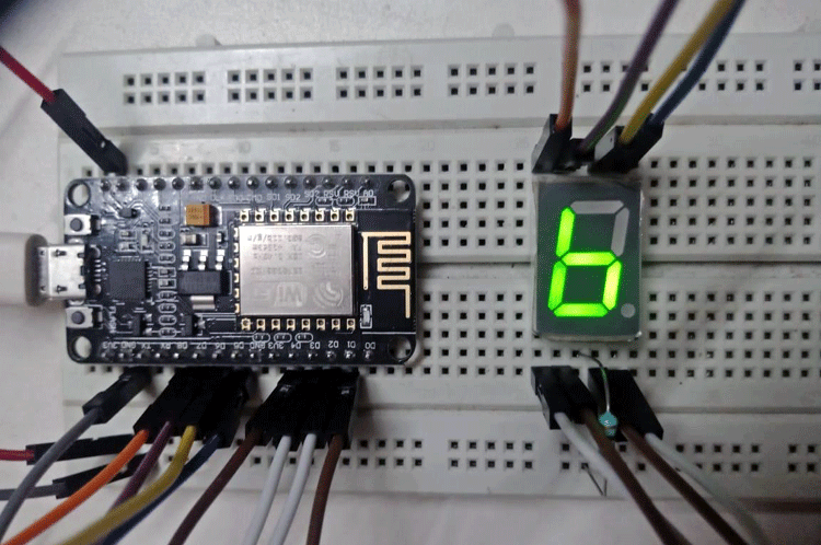
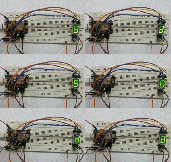
The figure above shows the final output of the project where the letter “b” is displayed on SSD
By learning how to use SSD with NodeMCU, the first step towards building thrilling projects has been taken. Here, the basic working principle of SSD is outlined, types of SSD are learned, programming NodeMCU is done.
const int A = 12;
const int B = 14;
const int C = 2;
const int D = 5;
const int E = 4;
const int F = 13;
const int G = 15;
const int DP = 0;
void setup() {
pinMode(A, OUTPUT);
pinMode(B, OUTPUT);
pinMode(C, OUTPUT);
pinMode(D, OUTPUT);
pinMode(E, OUTPUT);
pinMode(F, OUTPUT);
pinMode(G, OUTPUT);
pinMode(DP, OUTPUT);
}
void loop() {
zero();
delay(1000);
one();
delay(1000);
two();
delay(1000);
three();
delay(1000);
four();
delay(1000);
five();
delay(1000);
six();
delay(1000);
seven();
delay(1000);
eight();
delay(1000);
nine();
delay(1000);
a();
delay(1000);
b();
delay(1000);
c();
delay(1000);
d();
delay(1000);
e();
delay(1000);
f();
delay(1000);
}
void zero(){
digitalWrite(A, HIGH);
digitalWrite(B, HIGH);
digitalWrite(C, HIGH);
digitalWrite(D, HIGH);
digitalWrite(E, HIGH);
digitalWrite(F, HIGH);
digitalWrite(G, LOW);
digitalWrite(DP, LOW);
}
void one(){
digitalWrite(A, LOW);
digitalWrite(B, HIGH);
digitalWrite(C, HIGH);
digitalWrite(D, LOW);
digitalWrite(E, LOW);
digitalWrite(F, LOW);
digitalWrite(G, LOW);
digitalWrite(DP, LOW);
}
void two(){
digitalWrite(A, HIGH);
digitalWrite(B, HIGH);
digitalWrite(C, LOW);
digitalWrite(D, HIGH);
digitalWrite(E, HIGH);
digitalWrite(F, LOW);
digitalWrite(G, HIGH);
digitalWrite(DP, LOW);
}
void three(){
digitalWrite(A, HIGH);
digitalWrite(B, HIGH);
digitalWrite(C, HIGH);
digitalWrite(D, HIGH);
digitalWrite(E, LOW);
digitalWrite(F, LOW);
digitalWrite(G, HIGH);
digitalWrite(DP, LOW);
}
void four(){
digitalWrite(A, LOW);
digitalWrite(B, HIGH);
digitalWrite(C, HIGH);
digitalWrite(D, LOW);
digitalWrite(E, LOW);
digitalWrite(F, HIGH);
digitalWrite(G, HIGH);
digitalWrite(DP, LOW);
}
void five(){
digitalWrite(A, HIGH);
digitalWrite(B, LOW);
digitalWrite(C, HIGH);
digitalWrite(D, HIGH);
digitalWrite(E, LOW);
digitalWrite(F, HIGH);
digitalWrite(G, HIGH);
digitalWrite(DP, LOW);
}
void six(){
digitalWrite(A, HIGH);
digitalWrite(B, LOW);
digitalWrite(C, HIGH);
digitalWrite(D, HIGH);
digitalWrite(E, HIGH);
digitalWrite(F, HIGH);
digitalWrite(G, HIGH);
digitalWrite(DP, LOW);
}
void seven(){
digitalWrite(A, HIGH);
digitalWrite(B, HIGH);
digitalWrite(C, HIGH);
digitalWrite(D, LOW);
digitalWrite(E, LOW);
digitalWrite(F, LOW);
digitalWrite(G, LOW);
digitalWrite(DP, LOW);
}
void eight(){
digitalWrite(A, HIGH);
digitalWrite(B, HIGH);
digitalWrite(C, HIGH);
digitalWrite(D, HIGH);
digitalWrite(E, HIGH);
digitalWrite(F, HIGH);
digitalWrite(G, HIGH);
digitalWrite(DP, LOW);
}
void nine(){
digitalWrite(A, HIGH);
digitalWrite(B, HIGH);
digitalWrite(C, HIGH);
digitalWrite(D, HIGH);
digitalWrite(E, LOW);
digitalWrite(F, HIGH);
digitalWrite(G, HIGH);
digitalWrite(DP, LOW);
}
void a(){
digitalWrite(A, HIGH);
digitalWrite(B, HIGH);
digitalWrite(C, HIGH);
digitalWrite(D, LOW);
digitalWrite(E, HIGH);
digitalWrite(F, HIGH);
digitalWrite(G, HIGH);
digitalWrite(DP, LOW);
}
void b(){
digitalWrite(A, LOW);
digitalWrite(B, LOW);
digitalWrite(C, HIGH);
digitalWrite(D, HIGH);
digitalWrite(E, HIGH);
digitalWrite(F, HIGH);
digitalWrite(G, HIGH);
digitalWrite(DP, LOW);
}
void c(){
digitalWrite(A, HIGH);
digitalWrite(B, LOW);
digitalWrite(C, LOW);
digitalWrite(D, HIGH);
digitalWrite(E, HIGH);
digitalWrite(F, HIGH);
digitalWrite(G, LOW);
digitalWrite(DP, LOW);
}
void d(){
digitalWrite(A, LOW);
digitalWrite(B, HIGH);
digitalWrite(C, HIGH);
digitalWrite(D, HIGH);
digitalWrite(E, HIGH);
digitalWrite(F, LOW);
digitalWrite(G, HIGH);
digitalWrite(DP, LOW);
}
void e(){
digitalWrite(A, HIGH);
digitalWrite(B, LOW);
digitalWrite(C, LOW);
digitalWrite(D, HIGH);
digitalWrite(E, HIGH);
digitalWrite(F, HIGH);
digitalWrite(G, HIGH);
digitalWrite(DP, LOW);
}
void f(){
digitalWrite(A, HIGH);
digitalWrite(B, LOW);
digitalWrite(C, LOW);
digitalWrite(D, LOW);
digitalWrite(E, HIGH);
digitalWrite(F, HIGH);
digitalWrite(G, HIGH);
digitalWrite(DP, LOW);
}

