Pulse Width Modulation (PWM) is a type of analog modulating technique in which the duration or width of the pulse changes in accordance with the time. It is a commonly used technique to produce a continuous pulse signal with a defined frequency and duty cycle. In short, PWM is about changing the width of a pulse while the frequency remains constant.
With a PWM signal, you can easily control the speed of the servo motor or the brightness of an LED. Since generic microcontrollers can only provide Logic 1 (High) or Logic 0 (Low) on their output pins, they cannot provide a varying analog voltage unless it has a Digital to Analog converter (DAC) built-in or its connected externally. In such a case, the microcontroller can be programmed to output a Pulse Width Modulation (PWM) with a varied duty cycle which can then be converted to the varying analog voltage. We have previously used PWM peripheral in many other microcontrollers. Take a look.
- ARM7-LPC2148 PWM Tutorial: Controlling Brightness of LED
- Pulse width Modulation (PWM) using MSP430G2: Controlling Brightness of LED
- Generating PWM using PIC Microcontroller with MPLAB and XC8
- Pulse width Modulation (PWM) in STM32F103C8: Controlling Speed of DC Fan
- Generating PWM signals on GPIO pins of PIC Microcontroller
- Raspberry Pi PWM Tutorial
- PWM Tutorial with ESP32
- AC Phase Angle Controle for Light Dimmers
So in this tutorial, we will interface an LED with a generic STM8S microcontroller that is controlled using a PWM signal generated from the microcontroller and we will program the microcontroller using STVD and Cosmic C compiler. Before that, let's understand some basics of a PWM Signal.
Understanding the Basic of PWM Signal
As you may have heard, PWM stands for Pulse Width Modulation. It is an analog modulation technique that is used in a plethora of different applications and projects. An image of a PWM signal is shown below.
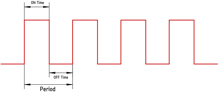
The image you are seeing above is a generic square wave that has the same ON time and OFF time. Now, let's say the total period of the square wave is 1 sec that means the on-time of the square wave and the off-time of the square wave is also 500ms. Therefore, if we connect an LED and power it up with this square wave, the LED will be on for half of the period and it will be off for half of the period. It will look like the LED is glowing in half brightness.
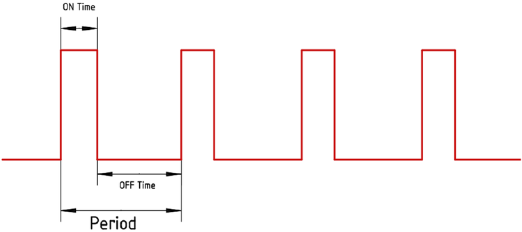
In the above image, you can see that we have reduced the duty cycle, if we consider the same 1S period, we have an On-Time of 250ms and an OFF time of 750ms. Now, if we connect the same LED, we will observe that the LED will be much more dimmer because the duty cycle is reduced. If you want to know more and learn about Pulse Width Modulation (PWM), you can check out the linked article.
Here are few PWM examples with other Microcontroller:
- Generating PWM using PIC Microcontroller with MPLAB and XC8
- Servo Motor Control with Raspberry Pi
- Arduino Based LED Dimmer using PWM
- Pulse width Modulation (PWM) using MSP430G2
Check all the PWM-related projects here.
STM8S PWM Generator Circuit: Hardware Setup and Requirement
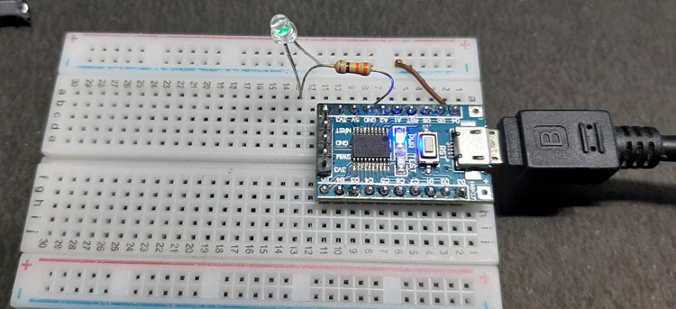
As we are controlling the LED using PWM, an LED is required to be interfaced with the STM8S board. Since an LED is available on the STM8S development board, I will be using that for demonstration. We also need the STM8S development board as well as the ST-LINK programmer. In addition to that, we need a 5V power supply to power the board since the development board has an onboard micro USB cable we will be using that to power the board.
Circuit Diagram for STM8S Microcontroller Based LED Dimmer
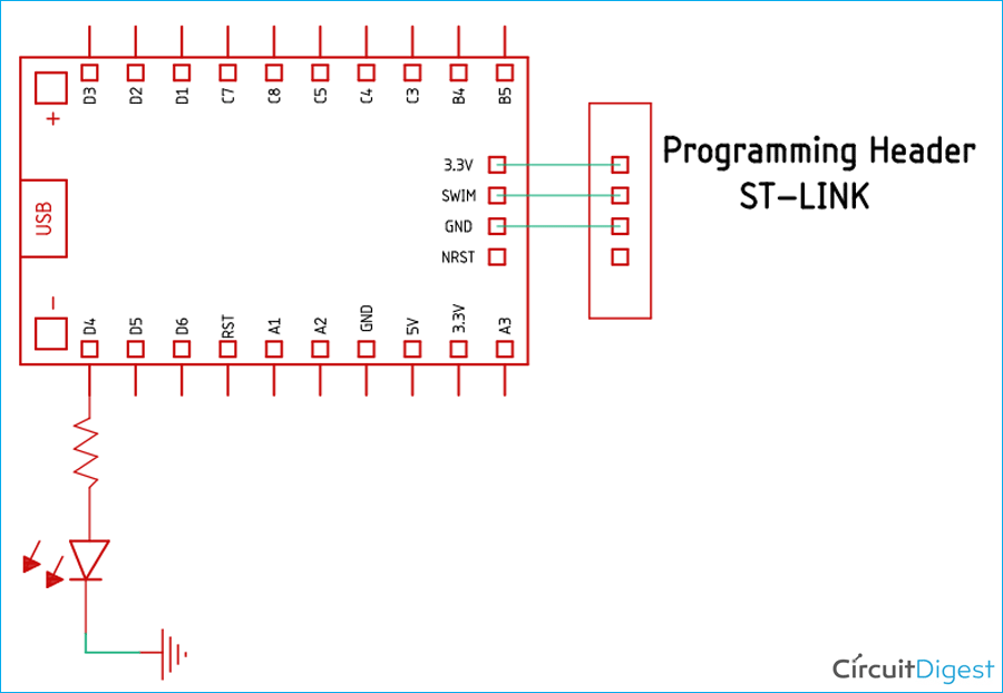
To program the circuit, we have connected an ST-Link V2 programmer to the 3.3V, SWIM, and the Ground pin of the STM8S development board. The most interesting thing about an STM8 microcontroller is that it only requires one pin that is the SWIM pin to program the microcontroller.
As you can see in the above schematic, a test LED is attached to the development board and it's connected to port 1.4 on the extreme left of the board
PWM Pins on ST Micro STM8S Microcontroller
The STM8S has 20 pins out of which 8 pins can be configured as PWM. The image below shows the PWM pins marked in the red square box. These pins are also GPIO pins that can be used for other functions.
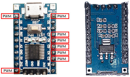
As we can see in the above image the marked pins can generate PWM signals. So we will use one of those in the board to produce PWM signals. However, enabling PWM will disable other functionalities so we need to be careful which pin we choose to configure as PWM. Since we are building this circuit for demonstration online, we will use the PIN D4 to generate a PWM signal.
Programming the STM8s Microcontroller To Generate the PWM signal
Create a workspace and new project as we discussed in our Getting Started with STM8S Microcontroller tutorial. You can either add all the header and source files or only add the gpio, timer2, config, and stm8s files. Open the main.c file and start writing your program.
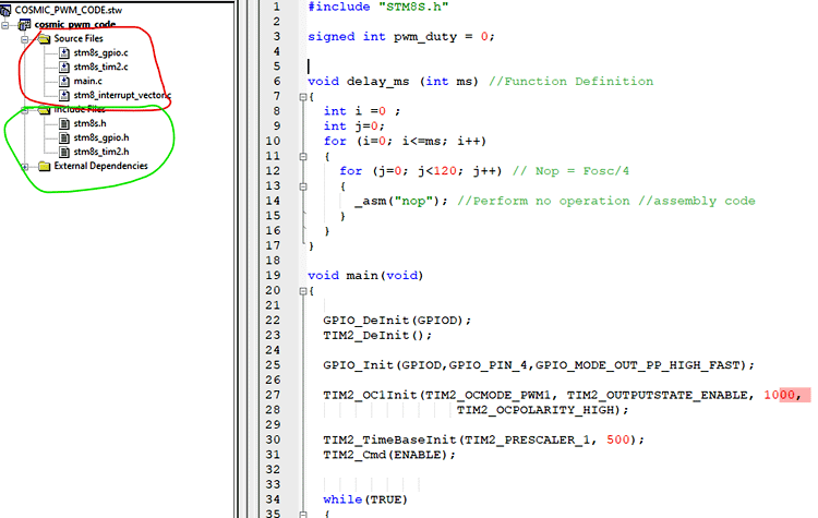
Make sure you have included the header files as shown in the image above. Open the main.c file and start the code. The complete main.c code can be found at the bottom of this page and you will also be able to download the project file from there. The explanation of the code is as follows, you can also refer to the SPL User manual or the video linked at the bottom of this page if you are confused about the coding part.
Before we start the coding process, you need to include stm8s_gpio.c, stm8s_tim2.c, and in the source folder and the header folder you need to include stm8s_gpio.h, stm8s_tim2.h. You can get these header files from STM8S103F3P6 SPL GitHub Repository. Once that is done, we begin our code by including all the required libraries and we define all the necessary variables. For this experimental code, we just need to hold the PWM value in a single variable which is why we have included a variable called pwm_duty.
#include "STM8S.h"
signed int pwm_duty = 0;
Once we have declared all the libraries and the variable, we need to build our delay function because the cosmic c compiler does not offer any predefined delay functions. We will use an assembly instruction NOP that takes only one clock cycle. And since the core of the microcontroller is running at 2MHz, we can easily guestimate the delay. For that reason, we are putting the delay in conjunction with two for loops. This is the easiest and the most accurate way to make a delay for the cosmic C compiler.
void delay_ms (int ms) //Function Definition
{
            for (int i=0; i<=ms; i++)
                        for (int j=0; j<120; j++) // Nop = Fosc/4
                                    _asm("nop"); //Perform no operation //assembly code
}
Next, we will look into our main loop. For this section, we need to look at SPL User Manual. We start the main function by Deinitilizing the GPIO pin and the Timer2. If the GPIO or the Timer have been previously used for some other application, then it should be initialized before we use them. It's not mandatory but it’s a good practice.
GPIO_DeInit(GPIOD);
TIM2_DeInit();
Next, we have to declare the pins as output, we set up the Timer2 with the help of the TIM2_OC1Init() function and we have used a Prescaler in the timer to achieve a PWM frequency of 4KHz. We did it with the help of TIM2_TimeBaseInit() function. Once that is done, we enable the timer with the help of TIM2_Cmd(ENABLE) function. For this project, we have decided to use PIN D4 on the board which is a PWM capable PIN.
GPIO_DeInit(GPIOD);
TIM2_DeInit();
GPIO_Init(GPIOD,GPIO_PIN_4,GPIO_MODE_OUT_PP_HIGH_FAST);
TIM2_OC1Init(TIM2_OCMODE_PWM1, TIM2_OUTPUTSTATE_ENABLE, 1000,
                   TIM2_OCPOLARITY_HIGH);
TIM2_TimeBaseInit(TIM2_PRESCALER_1, 500);
TIM2_Cmd(ENABLE);
Next, we have our infinite loop. In the infinite loop, we set up our for loops and we enable the capture and compare statements that will enable us to set the PWM channels.
  while(TRUE){
    for(pwm_duty = 0; pwm_duty < 1000; pwm_duty += 2){
      TIM2_SetCompare1(pwm_duty);
      delay_ms(10);
                        }
    for(pwm_duty = 1000; pwm_duty > 0; pwm_duty -= 2){
      TIM2_SetCompare1(pwm_duty);
      delay_ms(10);
    }
  }
The above code is responsible for generating the PWM signal, because in the first for loop the PWM signal will go from high to low, and because of the next for loop, the PWM signal will go from low to high and the cycle will continue.
Generating PWM Signal Using STM8S
Compile the code and upload it to your STM8S development board. If you get any compiling errors, make sure you have added all the header files and source files as discussed earlier. Once the code is uploaded, you should see the brightness of the attached LED on pin D4 will change.
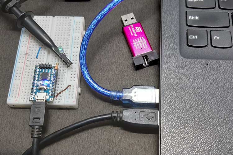
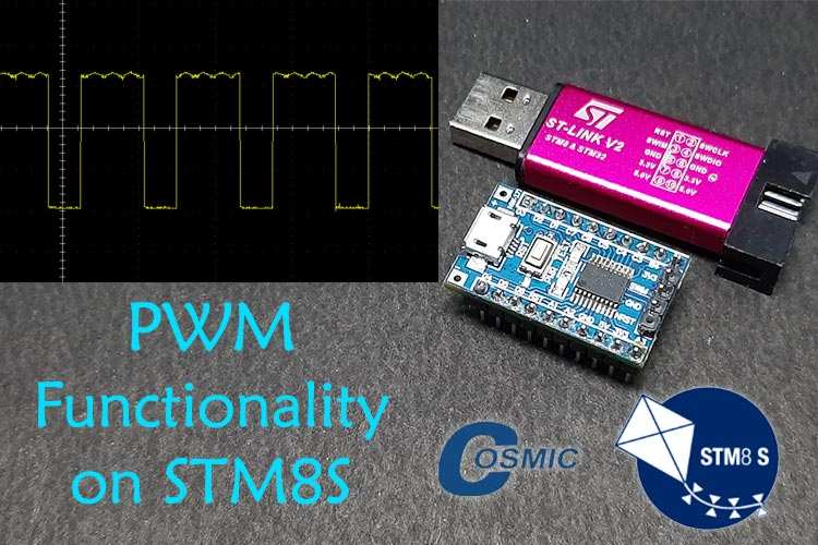
Once all that was done, we observe a PWM signal in our oscilloscope.

