Pulse Width Modulation (PWM) is a commonly used technique in microcontrollers to produce a continuous pulse signal with a defined frequency and duty cycle. In short, PWM is about changing the width of a pulse while the frequency is constant.
A PWM signal is mostly used in controlling a servo motor or brightness of an LED. Also, since microcontrollers can only provide Logic 1 (High) or Logic 0 (Low) on its output pins, it cannot provide a varying analog voltage unless a DAC or Digital to Analog converter is used. In such a case, the microcontroller can be programmed to output a PWM with a varied duty cycle which can then be converted to the varying analog voltage. We have previously used PWM peripheral in many other microcontrollers as well.
- ARM7-LPC2148 PWM Tutorial: Controlling Brightness of LED
- Pulse width Modulation (PWM) using MSP430G2: Controlling Brightness of LED
- Generating PWM using PIC Microcontroller with MPLAB and XC8
- Pulse width Modulation (PWM) in STM32F103C8: Controlling Speed of DC Fan
- Generating PWM signals on GPIO pins of PIC Microcontroller
- Raspberry Pi PWM Tutorial
- PWM Tutorial with ESP32
In this tutorial, we will interface an LED that will be controlled using this PWM signal from the N76E003 microcontroller unit. We will evaluate what kind of hardware setup we require and how we should program our microcontroller. Before that, let's understand some basics of a PWM Signal.
Basics of PWM Signal
In the below image a constant PWM signal is shown.

The above image is nothing but a constant square wave with the same ON time and the same OFF time. Suppose, the total period of the signal is 1 Second. Thus the on time and off time is 500ms. If an LED is connected across this signal, the LED will turn on for 500ms and turn off for 500ms. Therefore, in perspective view, the LED will lit up with half of the actual brightness if it is turned on to a direct 5V signal without any off time.

Now as shown in the above image, if the duty cycle is changed, the LED will lit up with 25% of actual brightness using the same principle as discussed before. If you want to know more and learn about Pulse Width Modulation (PWM), you can check out the linked article.
Hardware Setup and Requirement
As the requirement of this project is to control LED using PWM. An LED is required to be interfaced with N76E003. Since an LED is available in the N76E003 development board, it will be used in this project. No other components are required.
Not to mention, we need the N76E003 microcontroller based development board as well as the Nu-Link Programmer. An additional 5V power supply unit may be required if the programmer is not used as a power source.
Circuit Diagram for Nuvoton N76E003 Microcontroller LED Dimming
As we can see in the below schematic, the Test LED is available inside the development board and it is connected on port 1.4. On the extreme left, the programming interface connection is shown.
PWM Pins on N76E003 Nuvoton Microcontroller
The N76E003 has 20 pins out of which 10 pins can be used as PWM. The below images is showing the PWM pins highlighted in the red square box.
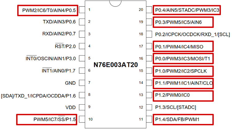
As we can see, the highlighted PWM pins can also be used for other purposes. However, this other purpose of the pins will not be available when the pins are configured for PWM output. Pin 1.4 which is used as a PWM output pin, it'll lose the other functionality. But, that is not a problem as another functionality is not required for this project.
The reason behind choosing pin 1.4 as an output pin is because the inbuilt Test LED is connected on that pin in the development board, thus we do not require external LEDs. However, in this microcontroller out of 20 pins, 10 pins can be used as a PWM output pin and any other PWM pins can be used for output related purposes.
PWM Registers and Functions in N76E003 Nuvoton Microcontroller
N76E003 uses system clock or Timer 1 overflow divided by a PWM clock with Prescaler selectable from 1/1 ~ 1/128. The PWM period can be set using the 16-bit period register PWMPH and PWMPL register.
The microcontroller has six individual PWM registers that generate six PWM signals called PG0, PG1, PG2, PG3, PG4, and PG5. However, the period is same for each PWM channels because they share the same 16-bit period counter but the duty cycle of each PWM can be different from others as each PWM uses different 16-bit duty cycle register named as {PWM0H, PWM0L},{PWM1H, PWM1L}, {PWM2H, PWM2L},{PWM3H, PWM3L},{PWM4H, PWM4L}, and {PWM5H, PWM5L}. Thus, in N76E003, six PWM outputs can be generated independently with different duty cycles.
Unlike with other microcontrollers, enabling the PWM does not set the I/O pins into their PWM output automatically. Thus, the user needs to configure the I/O output mode.
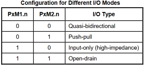
So, whatever is required for the application, the first step is to determine or select which one or two or even more than two I/O pins as PWM output. After selecting one, the I/O pins need to be set as Push-Pull mode or Quasi-bidirectional for generating the PWM signal. This can be selected using the PxM1 and PxM2 register. These two registers set the I/O modes where the x stands for the Port number (For example, Port P1.0 the register will be P1M1 and P1M2, for P3.0 it will be P3M1 and P3M2, etc.)
The configuration can be seen in the below image-
Then, the next step is to enable the PWM in that particular I/O pin(s). To do this, the user needs to set the PIOCON0 or PIOCON1 registers. The register is dependent on the pin mapping as PIOCON0 and PIOCON1 control different pins dependent on the PWM signals. The configuration of these two registers can be seen in the below image-

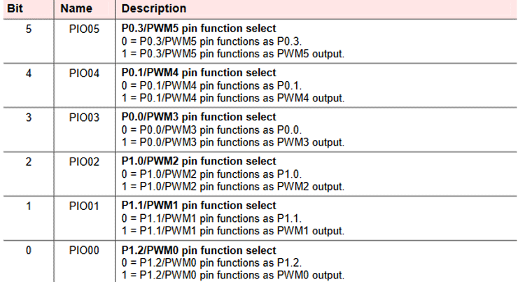
As we can see, the above register controls 6 configurations. For the rest, use the PIOCON1 register.

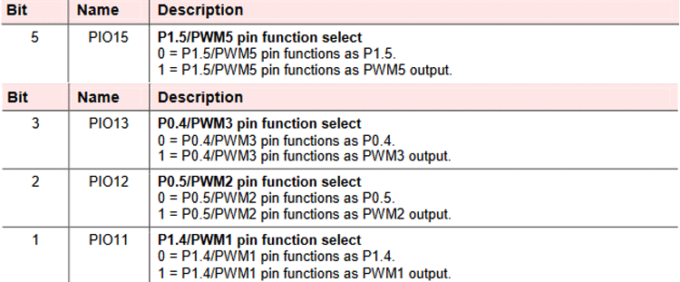
Thus, the above register controls the rest 4 configurations.
PWM Operating Modes in Nuvoton N6E003 Microcontroller
The next step is to select the PWM operation modes. Each PWM supports three operations modes - Independent, Synchronous, and Dead-Time enable mode.
Independent mode provides the solution where the six PWM signals can be generated independently. This is required maximum of times when LED related operations or buzzers need to be turned on and controlled.
The Synchronous mode sets the PG1/3/5 in the same in-phase PWM output, the same as PG0/2/4, where the PG0/2/4 provides independent PWM output signals. This is mainly required for controlling three-phase motors.
The Dead-Time insertion mode is a little bit complex and applied in real motor applications, especially in industrial applications. In such applications, a complementary PWM output needs to be “dead-time” insertion that prevents damaging of the power switching devices such as GPIBs. The configurations are set in this mode in a way that the PG0/2/4 provides PWM output signals in the same way as independent mode but PG1/3/5 provides “out-phase PWM signals” output of PG0/2/4 correspondingly and ignore PG1/3/5 Duty register.
Above three modes can be selected using the below register configuration-

The next configuration is the selection of PWM types using the PWMCON1 register.

So, as we can see, two PWM types are available that can be selected using the above register. In edge-aligned, the 16-bit counter uses single-slope operation by counting up from 0000H to the set value of {PWMPH, PWMPL}, and then starting from 0000H. The output waveform is left-edge aligned.
But, in center-aligned mode, the 16-bit counter uses dual-slope operation by counting up from 0000H to {PWMPH, PWMPL} and then again goes from {PWMPH, PWMPL} to 0000H by counting down. The output is center aligned and it is useful for generating non-overlapping waveforms. Now finally the PWM control operations that can be checked in the below registers-
To set the clock source, use the CKCON clock control register.

The PWM output signal can also be masked using the PMEN register. Using this register, the user can mask the output signal by 0 or 1.

Next is the PWM Control Register-

The above register is useful to run the PWM, load new period and duty load, control the PWM Flag and clear the PWM Counter.
The associated bit configurations are shown below-
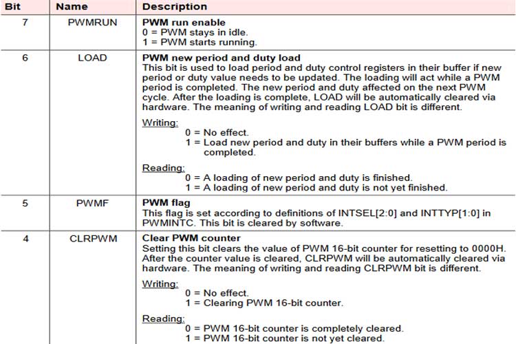
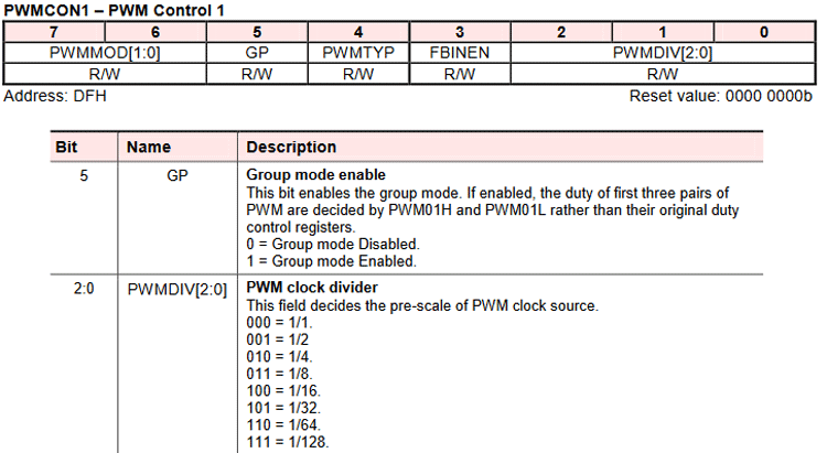
To set the clock divider, use the PWMCON1 register for the PWM clock divider. The 5th bit is used for the Group mode enabled grouped PWM and provides the same duty cycle for the first three PWM pairs.
Programming Nuvoton N76E003 for PWM
The coding is simple and the complete code used in for this tutorial can be found at the bottom of this page. The LED is connected to the P1.4 pin. Thus the P1.4 pin is needed to be used for PWM output.
In the main program, the settings are done in the respective order. Below lines of codes sets the PWM and configures the P1.4 pin as PWM output.
P14_PushPull_Mode;
This is used to set the pin P1.4 in push-pull mode. This is defined in the Function_define.h library as-
#define P14_PushPull_Mode
P1M1&=~SET_BIT4;P1M2|=SET_BIT4
PWM1_P14_OUTPUT_ENABLE;
The next lines used to enable the PWM in pin P1.4. This is also defined in the Function_define.h library as-
#define
PWM1_P14_OUTPUT_ENABLE
BIT_TMP=EA;EA=0;TA=0xAA;TA=0x55;SFRS|=0x01;PIOCON1|=0x02;TA=0xAA;TA=0x55;SFRS&=0xFE;EA=BIT_TMP                                            //P1.4 as PWM1 output enable
PWM_IMDEPENDENT_MODE;
The below code is used to set the PWM in independent mode. In the Function_define.h library, it is defined as-
#define
PWM_IMDEPENDENT_MODE
PWMCON1&=0x3F
PWM_EDGE_TYPE;
Then we have to set the EDGE type PWM output. In the Function_define.h library, it is defined as-
#define
PWM_EDGE_TYPE
PWMCON1&=~SET_BIT4
set_CLRPWM;
Next, we have to clear the PWM counter value which is available in SFR_Macro.h library-
#define
set_CLRPWM
CLRPWM = 1
After that, the PWM clock is selected as the Fsys clock and the division factor used is the 64 division.
PWM_CLOCK_FSYS;
PWM_CLOCK_DIV_64;
Both are defined as-
#define   PWM_CLOCK_FSYS   CKCON&=0xBF
#define   PWM_CLOCK_DIV_64  PWMCON1|=0x06;PWMCON1&=0xFE
PWM_OUTPUT_ALL_NORMAL;
Below line of code is used to mask the output PWM signal by 0 defined as-
#define PWM_OUTPUT_ALL_NORMAL PNP=0x00
set_PWM_period(1023);
Then we have to set the period time of the PWM signal. This function sets the period in PWMPL and PWMPH register. As this is a 16-bit register, the function uses a bit shifting method to set the PWM Period.
void set_PWM_period(unsigned int value){
  PWMPL = (value & 0x00FF);
  PWMPH = ((value & 0xFF00) >> 8);
}
However, other than the 1023 and 8-bit period, users can also use other values as well. Increasing the period results in smooth dimming or fading.
set_PWMRUN;
This will start the PWM that is defined in SFR_Macro.h library as-
#define set_PWMRUN PWMRUN = 1
Next, in the while loop, the LED is turned on and faded continuously.
 while(1){
          for(value = 0; value < 1024; value += 10){
          set_PWM1(value);
          Timer1_Delay10ms(3);
         }
         for(value = 1023; value > 0; value -= 10){
          set_PWM1(value);
          Timer1_Delay10ms(2);
         }
       }
    }
The duty cycle is set by the set_PWM1();, a function that sets the duty cycle in the PWM1L and PWM1H register.
void set_PWM1(unsigned int value){
  PWM1L = (value & 0x00FF);
  PWM1H = ((value & 0xFF00) >> 8);
  set_LOAD;
}
Flashing the Code And Testing the Output
Once the code is ready, just compile it and upload it to the controller. If you are new to the environment, check out getting started with Nuvoton N76E003 tutorial to learn the basics. As you can see from the below result, the code returned 0 warning and 0 Errors and flashed using the default flashing method by the Keil. The application starts working.
Rebuild started: Project: PWM
Rebuild target 'Target 1'
assembling STARTUP.A51...
compiling main.c...
compiling Delay.c...
linking...
Program Size: data=35.1 xdata=0 code=709
creating hex file from ".\Objects\pwm"...
".\Objects\pwm" - 0 Error(s), 0 Warning(s).
Build Time Elapsed:  00:00:05
The hardware is connected to the power source and it was working as expected. That is the brightness of the onboard LED reduced and then increased to indicate the change PWM duty cycle.
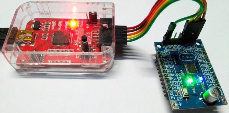
The complete working of this tutorial can also be found in the video linked below. Hope you enjoyed the tutorial and learned something useful if you have any questions, leave them in the comment section or you can use our forums for other technical questions.
#include "N76E003.h"
#include "SFR_Macro.h"
#include "Function_define.h"
#include "Common.h"
#include "Delay.h"
void set_PWM_period(unsigned int value);
void set_PWM1(unsigned int value);
void main(void){
                signed int value = 0;
                P14_PushPull_Mode;
                PWM1_P14_OUTPUT_ENABLE;
                PWM_IMDEPENDENT_MODE;
                PWM_EDGE_TYPE;
                set_CLRPWM;
                PWM_CLOCK_FSYS;
                PWM_CLOCK_DIV_64;
                PWM_OUTPUT_ALL_NORMAL;
                set_PWM_period(1023);
                set_PWMRUN;
                while(1){
                for(value = 0; value < 1024; value += 10){
                set_PWM1(value);
                Timer1_Delay10ms(3);
                }
                for(value = 1023; value > 0; value -= 10){
                set_PWM1(value);
                Timer1_Delay10ms(2);
                }
                                 }
    }
void set_PWM_period(unsigned int value){
  PWMPL = (value & 0x00FF);
  PWMPH = ((value & 0xFF00) >> 8);
}
void set_PWM1(unsigned int value){
  PWM1L = (value & 0x00FF);
  PWM1H = ((value & 0xFF00) >> 8);
  set_LOAD;
}Comments
I'm receiving following error
I'm receiving following error -
Build target 'Target 1'
compiling using-pwm.c...
linking...
*** WARNING L1: UNRESOLVED EXTERNAL SYMBOL
    SYMBOL:  BIT_TMP
    MODULE:  .\Objects\using-pwm.obj (USING_PWM)
*** WARNING L1: UNRESOLVED EXTERNAL SYMBOL
    SYMBOL:  _TIMER1_DELAY10MS
    MODULE:  .\Objects\using-pwm.obj (USING_PWM)
*** WARNING L2: REFERENCE MADE TO UNRESOLVED EXTERNAL
    SYMBOL:  BIT_TMP
    MODULE:  .\Objects\using-pwm.obj (USING_PWM)
    ADDRESS: 080EH
*** WARNING L2: REFERENCE MADE TO UNRESOLVED EXTERNAL
    SYMBOL:  BIT_TMP
    MODULE:  .\Objects\using-pwm.obj (USING_PWM)
    ADDRESS: 0827H
*** WARNING L2: REFERENCE MADE TO UNRESOLVED EXTERNAL
    SYMBOL:  _TIMER1_DELAY10MS
    MODULE:  .\Objects\using-pwm.obj (USING_PWM)
    ADDRESS: 0864H
*** WARNING L2: REFERENCE MADE TO UNRESOLVED EXTERNAL
    SYMBOL:  _TIMER1_DELAY10MS
    MODULE:  .\Objects\using-pwm.obj (USING_PWM)
    ADDRESS: 0896H
Program Size: data=11.0 xdata=0 code=197
creating hex file from ".\Objects\using-pwm"...
".\Objects\using-pwm" - 0 Error(s), 6 Warning(s).
Build Time Elapsed:  00:00:01
Can you tell me what may be the reason?
I have setup the environment as described in your Getting Started... article. Blinking LED program working fine.
is obve problem solved ?…
is obve problem solved ? what should required for this problem pls help. im stuck.
Define the bit BIT_TMP in…
Define the bit BIT_TMP in your main file and write new function of TIMER1_DELAY10MS in main file to solve the error for _TIMER1_DELAY10MS.
im also facing same problem…
im also facing same problem i did'nt get what actaully do pls explain in details
Hi Sir Am using MS51FB9AE ,…
Hi Sir
Am using MS51FB9AE ,& switch for controlling AC FAN speed . Can you kindly help me to start with coding of same
Can you help me with doing…
Can you help me with doing the same for a mm32
f0020 microntroller


Dear Friend,
I want to make program of Buton Event using Nuvoton N76E003
Can you please help me program to detect long Press, Short press of a single push button,
Single button for Multitasking
Please guide and share the program if possible