A rotary encoder is a type of electromechanical position sensor that can be used to identify the angular position of the rotary shaft. This type of sensor or module generates an electrical signal based on the movement and direction of the rotary shaft. This encoder is constructed with mechanical parts thus sensors are very robust, and can be used in many applications like robots, computer mice, CNC machines, and printers. There are two types of rotary encoder: one is an absolute encoder and another is an incremental encoder. For this article, we are going to use the incremental one and will let you know all the details about it. So without further ado let's get right into it.
Rotary Encoder Module Pinout
The Rotary Encoder Module has 5 pins; those are GND, +(VCC), SW(Switch), DT, and CLK. All the pins of this sensor module are digital, except VCC and Ground. The Pinout of a Rotary Encoder Module is shown below:
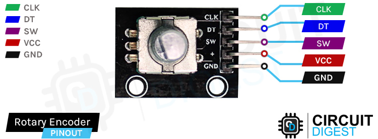
GND is the ground pin of the Rotary Encoder Module and it should be connected to the ground pin of the Arduino.
VCC is the power supply pin of the Rotary Encoder Module that can be connected to 5V or 3.3V of the supply.
SW stands for the switch pin of the rotary encoder. The rotary encoder we are using has a button inside the rotary encoder that activates if the top of the lever is pressed. This button is active LOW.
DT This pin is the same as the CLK output, but it lags the CLK pin by 90 degrees.
CLK is the main pin of the encoder module. Each time the knob is rotated the clock output goes from High to Low.
This device features an auto and manual mode function; users can enable auto speed control mode by inputting the desired temperature range(Min and Max Value) and clicking on the Enable Auto Mode button. If the slider is moved while the auto mode is enabled, the device automatically reverts back to manual speed control mode.
How Does a Rotary Encoder Module Work?
If we tear down the rotary encoder, we will see that there is a disk with lots of holes cut into it. The encoder plate is connected to common ground and either two contacts are shown below.

When the shaft of the encoder is turned, the Output A and Output B terminals come in contact with the common plate in a particular order that depends on the direction of rotation. If the encoder wheel is rotating in a clockwise direction, output A will get connected first and after that, output B will get connected to the common plate. If the encoder is rotating in the counter counter-clockwise direction the opposite will happen, but at the end of the day, the signal generated by output A and output B will always be 90* out of phase with each other.
In the above animation, if we turn the shaft of the encoder clockwise, the pin A connects first and then pin B. By tracking which pin is connected first and second, we can determine the direction of rotation, therefore we can increment or decrement a counter according to the direction of rotation.
Rotary Encoder Module – Parts
This is a cheap and easy-to-use module that can be used in many different applications. This sensor, depending on the direction of the rotation, generates a digital signal on its DATA and clock pin. If the data pin is leading the CLK pin by 90 degrees that means the encoder is rotating in the clockwise direction and the same is true for the opposite direction.
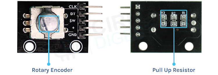
If you take a close look at the Rotary Encoder Module there is not much on the PCB itself, on the topside, we have the rotary encodes and header pins for connection and on the bottom side we only have pullup resistors. And that makes the whole of our rotary encoder module. As the rotary encoder is a mechanical device this can work with both 3.3V and 5V operating voltage.
Commonly Asked Questions about Rotary Encoder Module
Q. Where is the rotary encoder used?
Rotary encoders are used to control the speed of the conveyor belt as well as the direction of the movement. They are required in warehouse distribution systems, baggage handling systems, and case-packing systems.
Q. What are the three types of encoders?
An encoder detects the rotation of objects as a physical change amount by the sensor element, and finally transmits rotation/angle information to the outside as an electrical signal. An encoder is classified into four types: mechanical, optical, magnetic, and electromagnetic induction.
Q. What is the output of Rotary?
A rotary encoder, also called a shaft encoder, is an electro-mechanical device that converts the angular position or motion of a shaft or axle to an analog or digital output signals. There are two main types of rotary encoder: absolute and incremental.
Q. Is the rotary encoder better than the potentiometer?
The key advantage to using a rotary encoder over a potentiometer is that it can turn in the same direction indefinitely. In contrast, a potentiometer will typically turn one revolution, with the best resolution ones turning a maximum of ten times.
Q. What is an encoder jitter?
Encoder signal jitter is an inconsistency in encoder pulse shape in relation to another channel, often appearing as a backward and forward movement in the pulse. In the case of true signal jitter, the effect should show up on just one channel versus on all channels.
Circuit Diagram for Rotary Encoder Module
The module is made with very generic and readily available components, and all you need is three resistors and the encoder itself to build it yourself. The Schematic Diagram of the Rotary Encoder Module is shown below.
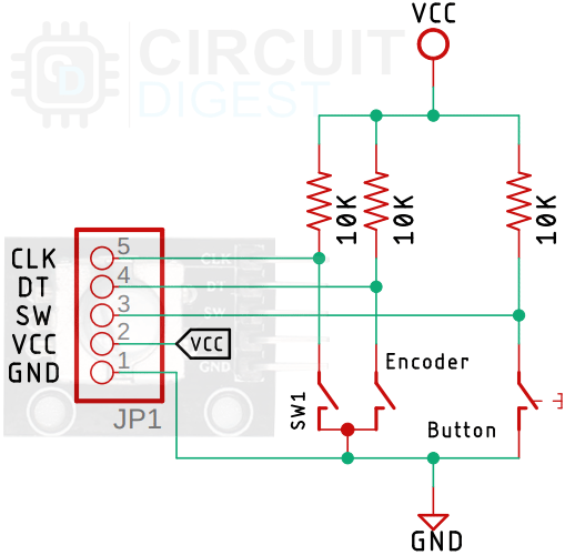
As you can see in the above image, there is not much in the rotary encoder module, all you need is three 10K pull-up resistors to build the module yourself. If you are building a PCB from the module this schematic can come in handy.
Arduino Rotary Encoder Module Circuit Connection Diagram
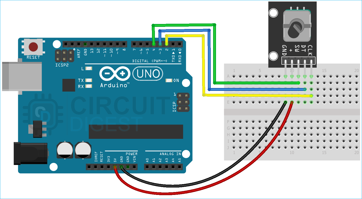
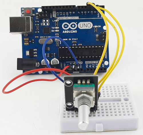
Now that we have completely understood how a Rotary Encoder Module works, we can connect all the required wires to the Arduino and write the code to get all the angular position data out from the sensor. The Connection Diagram of the Rotary Encoder Module with Arduino is shown below-
Connecting the rotary encoder module to the Arduino is very simple, we just need to connect the CLK and the DT pins of the rotary encoder to the Arduino's external interrupt pin that is the D2 and D3 in of the Arduino and we need to connect the SW pin to the D4 pin of the Arduino and we will configure that as pin change interrupt pin. That's all for the hardware connection from the rotary encoder to Arduino and we can now move to the code section.
Arduino Code for Interfacing Rotary Encoder Module with Arduino
The Arduino rotary encoder code to read angular data from the rotary encoder is shown below. The code is very simple and easy to understand. For this code, we will be using interrupts to get the angular data from the rotary encoder. We are using interrupts because the chance of error with interrupts is very less.
We start our code by including all the required libraries and we also define the Arduino pins for the clock, data, and button pins.
#include "PinChangeInterrupt.h"
#define CLK 2
#define DT 3
#define SW 4
Next, we have defined all the required variables for holding the button state and counter state for the rotary encoder.
int counter = 0;
int currentState;
int initState;
unsigned long bebounceDelay = 0;
Next, we have our setup function. In the setup function, we set the three pins that we have defined earlier as input and we also initialize the serial monitor window for debugging.
void setup() {
  pinMode(CLK, INPUT);
  pinMode(DT, INPUT);
  pinMode(SW, INPUT_PULLUP);
  // Setup Serial Monitor
  Serial.begin(9600);
Next, we read the current state of the CLK pin of the encoder and store it in the initState variable. This is important and without this step, the encoder counter will not work.
  // Read the initial state of CLK
  initState = digitalRead(CLK);
Finally, in the setup function, we have declared the interrupt and we configured it as CHANGE so that we could catch any interrupts that are from the encoder.
  attachInterrupt(0, encoder_value, CHANGE);
  attachInterrupt(1, encoder_value, CHANGE);
  attachPCINT(digitalPinToPCINT(SW), button_press, CHANGE);
}
Next, we have our loop section, the loop section will remain empty as we are doing nothing inside the loop section.
void loop(){
}
Next, we have our button_press() function, this function will be automatically called when an interrupt has occurred. Inside this function, we read the SW pin and check if the pin is low or not. If it's low then we wait for a certain amount of time to check if the button is actually pressed or if it's random noise. This way we can reduce the debouncing error from the button. If the button is pressed, we print Button pressed! Message on the serial monitor window.
void button_press()
{
  int buttonVal = digitalRead(SW);
  //If we detect LOW signal, button is pressed
  if (buttonVal == LOW) {
    if (millis() - bebounceDelay > 200) {
      Serial.println("Button pressed!");
    }
    debounceDelay = millis();
  }
}
Next, we have the encoder value function. In this function, we check the encoder position and its direction and we increment the counter according to the rotation of the encoder. If the rotation is in a clockwise direction we increment the counter, if it's in the counter-clockwise direction we decrement the counter.
void encoder_value() {
  // Read the current state of CLK
  currentState = digitalRead(CLK);
  // If last and current state of CLK are different, then we can be sure that the pulse occurred
  if (currentState != initState  && currentState == 1) {
    // Encoder is rotating counterclockwise so we decrement the counter
    if (digitalRead(DT) != currentState) {
      counter ++;
    } else {
      // Encoder is rotating clockwise so we increment the counter
      counter --;
    }
    // print the value in the serial monitor window
    Serial.print("Counter: ");
    Serial.println(counter);
  }
  // Remember last CLK state for next cycle
  initState = currentState;
}
This marks the end of the code portion of our code section and we can move on to the next section for this basic interfacing project with Arduino.
Working of the Arduino Rotary Encoder Module Circuit
The gif image below shows how the Rotary encoder works. You can see on the left-hand side, that I am turning the encoder module in the clockwise direction, and on the right-hand side, you can see the counter in the serial monitor is increasing its value. Once that is done, I pressed the button on the encode and on the serial monitor window and you can see the button pressed text.
Rotary Encoder Module not Working? Here is what you should do!
- Check if the VCC line and the ground line of the encoder module are properly connected to the VCC and ground line of the Arduino.
- If you are using the encoder without interruption in a project, there might be a chance that the other code in the loop function will create enough delay that the Arduino will be unable to process the encoder data.
- If the rotary encoder is producing a noise pulse it could be because the rotary encoder is old and it's producing jitters. There is no solution to this problem and you have to replace the encoder.
- As the rotary encoder is in an open environment, there can be dust accumulated around the shaft of the encoder, which can render the device useless. So cleaning the shaft solves many issues.
Projects using Arduino and Rotary Encoder Module
If you are interested in learning about PIC Microcontrollers and its working, this project might be what you are looking for, because in this project we have interfaced Rotary Encoder with a PIC microcontroller and explained how interrupt on PIC microcontroller works.
If you are looking for interesting project ideas with rotary encoders and a way to learn how the rotary encoder works, this project is for you. Because in this project we have interfaced a rotary encoder with Arduino and built a working function generator with it.
This is an excellent example of a rotary encoder and its use case. In this project, we explained what a PID controller is, and we have used an encoder motor to demonstrate the working of a PID controller. The motor we have used in this project is an encoder motor. The motor is named so because it has an encoder built in the backside of the motor in order to detect its position.
Supporting Files
#include "PinChangeInterrupt.h"
#define CLK 2
#define DT 3
#define SW 4
int counter = 0;
int currentState;
int initState;
unsigned long debounceDelay = 0;
void setup() {
pinMode(CLK, INPUT);
pinMode(DT, INPUT);
pinMode(SW, INPUT_PULLUP);
// Setup Serial Monitor
Serial.begin(9600);
// Read the initial state of CLK
initState = digitalRead(CLK);
// Call encoder_value() when any high/low changed seen
// on interrupt 0 (pin 2), or interrupt 1 (pin 3)
attachInterrupt(0, encoder_value, CHANGE);
attachInterrupt(1, encoder_value, CHANGE);
attachPCINT(digitalPinToPCINT(SW), button_press, CHANGE);
}
void loop()
{
}
void button_press()
{
int buttonVal = digitalRead(SW);
//If we detect LOW signal, button is pressed
if (buttonVal == LOW) {
if (millis() - debounceDelay > 200) {
Serial.println("Button pressed!");
}
debounceDelay = millis();
}
}
void encoder_value() {
// Read the current state of CLK
currentState = digitalRead(CLK);
// If last and current state of CLK are different, then we can be sure that the pulse occurred
if (currentState != initState && currentState == 1) {
// Encoder is rotating counterclockwise so we decrement the counter
if (digitalRead(DT) != currentState) {
counter ++;
} else {
// Encoder is rotating clockwise so we increment the counter
counter --;
}
// print the value in the serial monitor window
Serial.print("Counter: ");
Serial.println(counter);
}
// Remember last CLK state for next cycle
initState = currentState;
}

