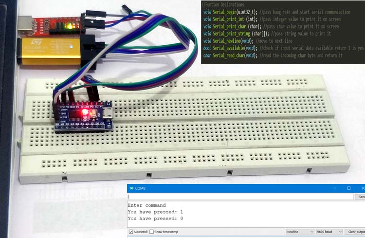
Programming a new microcontroller often takes a longer time due to the new register handling methods and not knowing what bit does exactly what. The same goes for debugging as well without saying. This is why programmers quite often use breakpoints in their code and step through it using a debugger. But using a debugger might need additional hardware (most times expensive) and also additional time. Being an Arduino fan boy, one thing we all can agree is using serial print statements for debugging and understanding our code makes life a lot easier. What is we can replicate the same on STM8s with cosmic C compiler and SPL libraries? Well, it is very much possible, and that is exactly what we are going to do in this third tutorial of our tutorial series. You also check the getting started with STM8S (tutorial 1) and STM8S GPIO control (tutorial 2) if you are completely new here. Also, we have also explored the possibility of Programming STM8S with Arduino for quick starters. All that being said let’s get into the tutorial.
Serial Communication on STM8S103F3P6
From the datasheet of STM8S103F3P6, we can see that our 8-bit controller supports UART communication in many different modes. The controller also has a clock output pin for synchronous UART communication and can also support SmarCard, IrDA, and LIN. But we will be exploring none of that in this tutorial just to stay away from complexity. We will learn how to do simple UART read and write.
The tutorial also provides a header file called stm8s103 serial.h using which you can perform simple UART commands like Serial begin, Serial read, serial print, etc. Basically, you will be able to print char, int, and string to the serial monitor and also read char from the serial monitor. At the end of this tutorial, you will be able to control an LED from the serial monitor and get feedback about the status of the LED. The header file mentioned above depends on the SPL libraries, so make sure you have followed the getting started tutorial.
Serial Communication Pins on STM8S103F3P6
Let’s start from the hardware side. Taking a quick look at the pinouts on the STM8S103F3P6 microcontroller given below, we can see that pins 1, 2, and 3 will be used for UART communication.
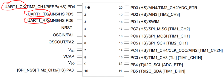
Among the three, pin 1 is the UART clock pin which will be used only during synchronous UART communication, so we won’t be needing it here. Pin 2 is the UART Transmitter pin and Pin 3 is the UART Receiver pin. Do note that these pins can also double up as an analog pin or normal GPIO pin.
Circuit Diagram for STM8S Serial Communication
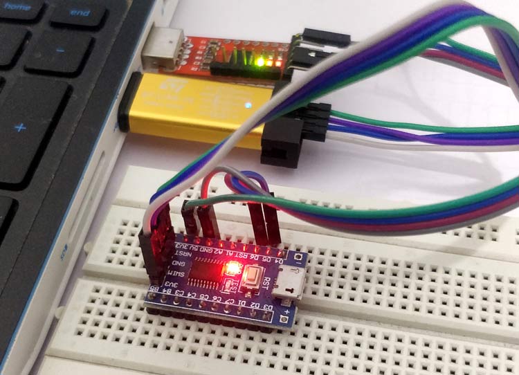
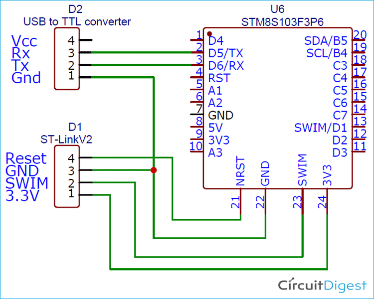
The circuit diagram is very simple here, we need to connect our ST-LINK 2 for programming and a USB to TTL converter for reading serial data. Do note that our STM8S controller works in 3.3V logic level, so make sure your USB to TTL converter also supports 3.3V logic. The complete circuit diagram is shown below.
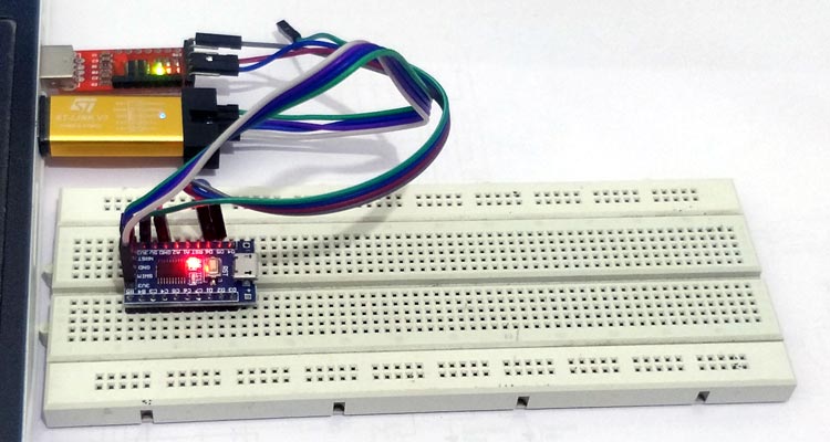
You have to connect your ST-link in one USB port and USB to TTL converter in another USB port of your laptop, so that you can both program and monitor data at the same time. The UART connection is simple, just connect the ground and Rx/Tx pin of your STM8S microcontroller to the Tx/Rx pins of the USB to TTL converter. Here I have powered the controller with the Vcc pin of ST-Link and have left the vss pin of TTL converter open, you can also do this the other way around. There are many types of USB to TTL converter in the market just make sure it can operate on 3.3V Logic signals and simple look for Tx, Rx, and GND pins and make the connection shown above. My hardware set-up is shown below.
To make a serial communication way, we have provided the STM8S_Serial.h header file. Using this header file, you can perform simple Arduino like functions for serial communication.

You can find all the required files for this project on our STM8S103F3_SPL Github page. If you only need this particular header file, you can download it from the below link.
Setting up STVD for Serial Communication
To work with serial communication, we will be using many using the STM8S_Serial.h header file function that we discussed earlier. But the library has other dependencies, many the SPL UART and Clock related header and C files. So from this point, it is better to include all the header and C files to our project to avoid a compilation error. My STVD work environment looks like this.
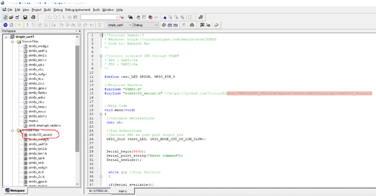
Make sure you have included all the SPL source files and Include file like we did in our first tutorial. And also ensure you have added the stm8s103_serial.h header file. There is no C file for this header.
Programming STM8S for Serial Communication
Once the STVD project setup is ready, we can begin writing our code in the main.c file. The complete code for this tutorial can be found at the bottom of this page. The explanation is as follows.
The first step is to include the required header files, here I have added the main header file (stm8s) and the stm8s_103_serial header file that we just downloaded.
//Required Headers
 #include "STM8S.h"
 #include "stm8s103_serial.h" //https://github.com/CircuitDigest/STM8S103F3_SPL/blob/master/stm8s103%20Libraries/stm8s103_Serial.h
Next, we are using the design macros to specify the input and output pins. Here will only be controlling the on-board LED which is connected to pin5 of port B, so we give it a name as test_LED.
#define test_LED GPIOB, GPIO_PIN_5 //test LED is connected to PB5
Moving on inside the main function, we will define the pin as an output. If you are not familiar with basic GPIO functions fall back to the STM8S GPIO tutorial.
//Pin defanitions
//Declare PB5 as push pull Output pin
GPIO_Init (test_LED, GPIO_MODE_OUT_PP_LOW_SLOW);
Then we initialize our serial communication ports at 9600 baud rates. For those who are new, 9600 is the rate of speed at which the data bits will be transferred during communication. If you set 9600 here, you also have to set the same on the monitoring software. Then we also print a string “Enter command” and move on to the next line.
Serial_begin(9600); //Initialize Serial communication at 9600 baud rate
Serial_print_string("Enter command"); //print a string
Serial_newline(); //move to next line
Moving on to the infinite while loop, we use the Serial_available function to check if there is any incoming serial data. If yes, we read and save it in a variable called ch and also print the same using Serial_print. Then if the received value is 0, we will turn off the LED and if it is 1, we will turn on the LED
   if(Serial_available())
     {
Serial_print_string("You have pressed: ");
ch = Serial_read_char();
Serial_print_char(ch);
Serial_newline();
if (ch == '0')
GPIO_WriteHigh(test_LED); //LED OFF
if (ch == '1')
GPIO_WriteLow(test_LED); //LED ON
}
With this, the programming for this tutorial is complete, just upload the code given at the bottom of this page and you should be able to control the LED from the serial monitor.
Controlling LED from Serial monitor
Once you have uploaded the code, you can open any serial monitor at 9600 baud rates. I have used the Arduino serial monitor itself for the ease of using it. Press the reset button and you should see the message “Enter a command”. Then if you enter 1 and press enter, the on-board led should turn on, similarly for 0, it should turn off.

The complete working can be found in the video linked at the bottom of this page. If you have any questions, please leave them in the comment section. You can also use our forums to post other technical questions.
STM8S Serial Library Deeper Look
For those curious minds who want to know what actually happens inside the STM8S103F3_Serial header file read on….
This header file works well for beginner level programming, but if you are using a different version of the STM8S controller or looking for some advanced options, you might want to tweak this header a bit or directly work with SPL libraries. I wrote this header file just as a ripe off from the UART1 header file, the explanation of my header file is as follows.
Reading a character from Serial Monitor
This function helps to read a single character that has been sent to the microcontroller from the serial monitor.
char Serial_read_char(void)
 {
                 while (UART1_GetFlagStatus(UART1_FLAG_RXE) == RESET);
                 UART1_ClearFlag(UART1_FLAG_RXNE);
                 return (UART1_ReceiveData8());
 }
We wait till the RXE flag is SET to complete reception and then clear the flag to acknowledge the reception. Finally, we send the received 8-bit data as the result of this function.
Printing a character to Serial Monitor
This function transmits a single character from a microcontroller to the serial monitor.
void Serial_print_char (char value)
 {
                 UART1_SendData8(value);
                 while (UART1_GetFlagStatus(UART1_FLAG_TXE) == RESET); //wait for sending
 }
The function simply writes the 8-bit value and waits till the transmission is complete by checking the UART1_FLAG_TXE to SET
Initializing Serial Communication
This function initializes serial communication at the required baud rate.
void Serial_begin(uint32_t baud_rate)
 {
                 GPIO_Init(GPIOD, GPIO_PIN_5, GPIO_MODE_OUT_PP_HIGH_FAST);
                 GPIO_Init(GPIOD, GPIO_PIN_6, GPIO_MODE_IN_PU_NO_IT);
                 UART1_DeInit(); //Deinitialize UART peripherals
                               UART1_Init(baud_rate,
                UART1_WORDLENGTH_8D,
                UART1_STOPBITS_1,
                UART1_PARITY_NO,
                UART1_SYNCMODE_CLOCK_DISABLE,
                UART1_MODE_TXRX_ENABLE); //(BaudRate, Wordlegth, StopBits, Parity, SyncMode, Mode)
                                UART1_Cmd(ENABLE);
 }
Apart from the baud rate, there are other parameters that have to be set for serial communication, like the number of data bits, number of stop bits, parity, etc. The most common one (similar to Arduino) is the 8-bit data with one stop bit and no parity and hence that will be the default setting. You can change it if required.
Printing an Integer to Serial Monitor
Most time, if we are using a serial monitor for debugging or monitoring, we might want to print a variable of type int to the serial monitor. This function does exactly that
void Serial_print_int (int number) //Funtion to print int value to serial monitor
 {
                 char count = 0;
                 char digit[5] = "";
                 while (number != 0) //split the int to char array
                 {
                                 digit[count] = number%10;
                                 count++;
                                 number = number/10;
                 }
                 while (count !=0) //print char array in correct direction
                 {
                                UART1_SendData8(digit[count-1] + 0x30);
                                while (UART1_GetFlagStatus(UART1_FLAG_TXE) == RESET); //wait for sending
                                count--;
                 }
 }
It takes in an integer value and converts it to character array in the first while loop, then in the second while loop, we will sending each of the characters similar to our print char function.
Printing a new line
This is a simple function to print a new line. The hexvalue to do that is “0x0a”, we are just sending it across using the 8-bit transmit command.
void Serial_newline(void)
 {
                 UART1_SendData8(0x0a);
                while (UART1_GetFlagStatus(UART1_FLAG_TXE) == RESET); //wait for sending
 }
Printing a string to serial monitor
Another useful function is to actually print strings on the serial monitor.
void Serial_print_string (char string[])
 {.
                 char i=0;
                 while (string[i] != 0x00)
                 {
                                UART1_SendData8(string[i]);
                                while (UART1_GetFlagStatus(UART1_FLAG_TXE) == RESET);
                                i++;
                }
 }
Again, this function also converts the string to char array and sends each character. As we know all strings end will null. So we just have to keep traversing and transmitting the characters till we reach the null 0x00.
Checking if serial data is available to read
This function checks if there is any serial data in the buffer ready to read.
bool Serial_available()
 {
                 if(UART1_GetFlagStatus(UART1_FLAG_RXNE) == TRUE)
                 return TRUE;
                 else
                 return FALSE;
 }
It checks for the flag UART1_FLAG_RXNE, if it is true, it returns true and if it is not, it returns false.
 /*Tutorial Number:3
 * Website: https://circuitdigest.com/search/node/STM8S
 * Code by: Aswinth Raj
 */
 /*Control on-board LED through USART
 * PD5 - UART1-Tx
 * PD6 - UART1-Rx
 */
 //Required Headers
 #include "STM8S.h"
 #include "stm8s103_serial.h" //https://github.com/CircuitDigest/STM8S103F3_SPL/blob/master/stm8s103%20Libraries/stm8s103_Serial.h
 #define test_LED GPIOB, GPIO_PIN_5
 //Main Code
 void main(void)
 {

//Variable declarations

char ch;

//Pin defanitions
//Declare PB5 as push pull Output pin

GPIO_Init (test_LED, GPIO_MODE_OUT_PP_LOW_SLOW);
Serial_begin(9600);
Serial_print_string("Enter command");
Serial_newline();
while (1) //Loop function
{
   if(Serial_available())
   {
Serial_print_string("You have pressed: ");
ch = Serial_read_char();
Serial_print_char(ch);
Serial_newline();

if (ch == '0')
GPIO_WriteHigh(test_LED); //LED OFF

if (ch == '1')
GPIO_WriteLow(test_LED); //LED ON
}
}
}Comments
Yes, there will be more tutorials on STM8S soon!!!!
Yes, there will be more tutorials on STM8S soon!!!!
Hi Is it possible to have a
Hi Is it possible to have a serial connection by adding stm8s105 board to Arduino without rx tx connection?
Hi thanks for good…
Hi thanks for good information.
can i ask how can get uart string ?
i need for running esp8266.



Nice! Are you going to do more with the STM8S?