Robots have slowly started to crawl into our society to make our life simpler. We can already find the six wheeled food delivery robots from Starship on the roads of UK, smartly navigating among the civilians to reach its destination. Every mobile robot which navigates into the environment should always be aware of its position and orientation with respect to the real world. There are many ways to achieve this by using different technologies like GPS, RF Triangulation, Accelerometers, Gyroscopes etc. Each technique has its own advantage and is unique by itself. In this Arduino LM393 speed sensor tutorial we will use the simple and easily available LM393 speed sensor module to measure some vital parameters like Speed, Distance travelled and Angle of the robot using Arduino. With these parameters the robot will be able to know its real world status and can use it to navigate safely.
Arduino is the most popular choice among hobbyists for building robots, from a simple line follower to a more complex self-balancing or floor cleaning robot. You can check all kind of robots in the Robotics section.
We will build a small robot that is powered by a lithium battery and drive it using a joystick. During the runtime we can measure the speed, distance and angle of the robot and display it real-time on the LCD display connected to Arduino. This project just helps you with measuring these parameters, once you are done with this you can use these parameters to operate your bot autonomously as required. Sounds interesting right? So let’s get started.
LM393 Speed Sensor Module (H206)
Before we get into the circuit diagram and code for the project, let us understand the LM393 Speed sensor Module as it plays a vital role in the project. The H206 Speed sensor module consists of an Infrared Light sensor integrated with a LM393 Voltage comparator IC hence the name LM393 Speed sensor. The module also consists of a grid plate which has to be mounted to the rotating shaft of the motor. All the components are labeled in below image.
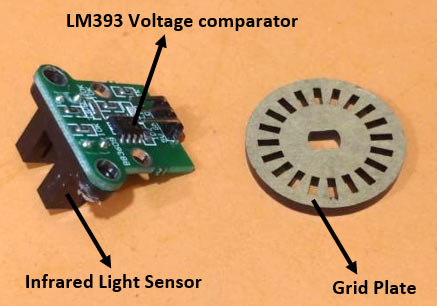
The Infrared Light sensor consists of an IR LED and a photo-transistor separated by a small gab. The entire sensor arrangement is placed in a black housing as shown above. The Grid plate consist of slots, the plate is arranged in between the gap of the Infrared Light Sensor in such a manner that the sensor can sense the gaps in grid plate. Each gap in the grid plate triggers the IR sensor when passing through the gap; these triggers are then converted into voltage signals using the comparator. The comparator is nothing but an LM393 IC from ON semiconductors. The module has three pins, two of which is used to power the module and one output pin is used to count the number of triggers.
H206 Sensor Mounting Arrangement
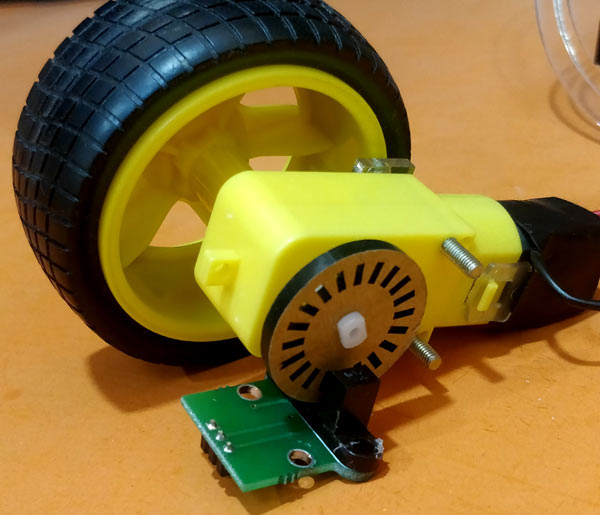
Mounting these types of sensors is a bit tricky. It can be mounted only to motors that have shaft protruded on both the side. One side of the shaft is connected to the wheel while the other side is used to mount the grid plate as shown above.
Since the wheel and plate is connected to the same shaft both rotates in the same speed and thus by measuring the speed of the plate we can measure the speed of the wheel. Make sure the gaps in the grid plate pass through the IR sensor, only then the sensor will be able to count the number of gaps that has passed through. You can also come up with your own mechanical arrangement to mount the sensor as long as it satisfies the specified condition. IR sensor is generally used in many Robotics projects to guide the robot about the obstacles.
The grid plate showed above have 20 slots (grids). This means that the sensor will find 20 gaps for one complete rotation of the wheel. By counting the number of gaps the sensor has detected we can calculate the distance traveled by the wheel, similarly by measuring how fast the sensor finds the gaps we can detect the speed of the wheel. In our robot we will have this sensor mounted to both the wheels and hence we can find the angle of the robot as well. However the angle of rotation can be more sensibly calculated using the Accelerometer or Gyroscope, learn here to interface Accelerometer and gyroscope with Arduino and give a try to measure rotational angle using them.
DIY Arduino LM393 Speed Sensor Robot Circuit Diagram
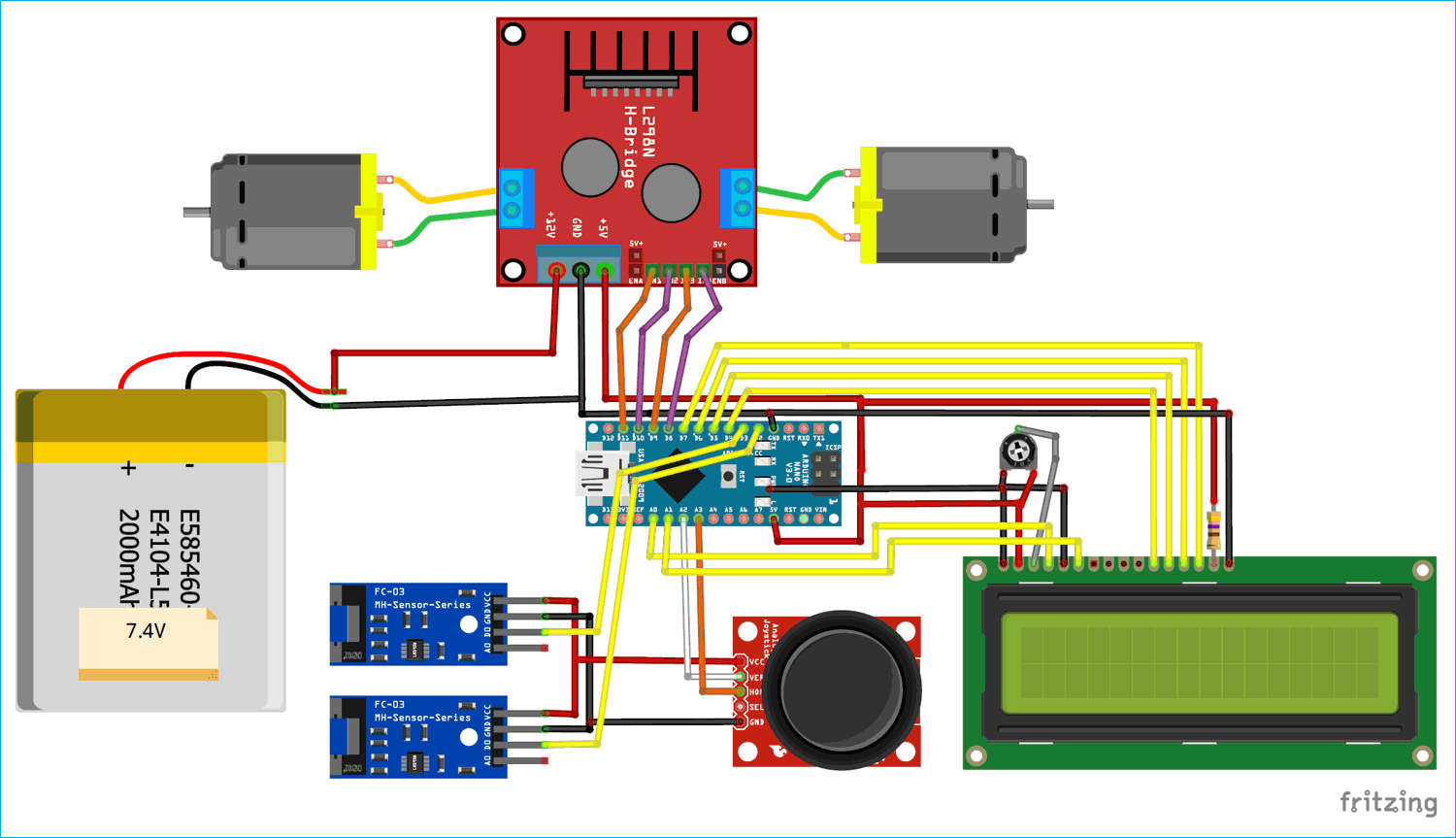
The complete circuit diagram of this Speed and distance sensing robot is shown below. The Bot consists of Arduino Nano as its brain, the two DC motors for the wheels is driven by the L298N H-Bridge Motor Driver module. The Joystick is used to Control the speed and direction of the bot and the two speed sensors H206 is used to measure the speed, distance and angel of the bot. The measured values are then displayed in the 16x2 LCD module. The potentiometer connected to the LCD can be used to adjust the contrast of the LCD and the resistor is used to limit the current flowing to the backlight of the LCD.
The complete circuit is powered by a 7.4V Lithium cell. This 7.4V is supplied to the 12V pin of the Motor driver module. The voltage regulator on the motor driver module then converters the 7.4V to regulated +5V which is used to power the Arduino, LCD, Sensors and Joystick.
The Motor is controlled by the digital pins 8,9,10 and 11 of the Arduino. Since the speed of the motor also has to be controlled we should supply PWM signals to positive terminal of the motor. Hence we have pin 9 and 10 which are both PWM capable pins. The X and Y values form the joystick is read using the Analog pins A2 and A3 respectively.
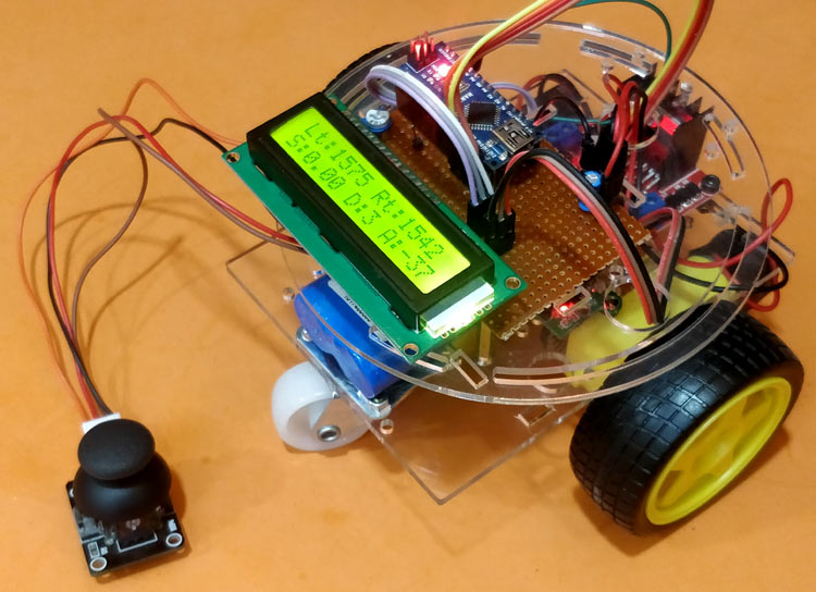
As we know the H206 sensor with generate a trigger when the gap in the grid plate is detected. Since these triggers should not always be read accurately to calculate the correct speed and distance both the trigger (output) pins are connected to the External interrupt pin 2 and 3 of the Arduino Board. Assemble the whole circuit on a chassis and mount the speed sensor as explained, my bot looked something like below after the connections were completed. You can also watch the video at the end of this page to know how the sensor was mounted.

Now that the hardware part is completed let us get into the logics of how we will be measuring the speed, distance and single of the bot and then proceed to the programming section.
Logic behind Measuring Speed with LM393 speed sensor module
From the sensor mounting set-up you should be aware that the LM393 speed sensor module (H206) measures only the gaps present in the grid plate. While mounting it should made sure that the wheel (whose speed should be measured) and the grid plate rotates in the same speed. Like here, since we have mounted both the wheel and the plate on the same shaft they will both rotate with the same speed obviously.
In our set-up we have mounted two sensors for each wheel to measure the angle of the bot. But if your aim is to measure only the speed and distance we can mount the sensor on any one wheel. The output of the sensor (trigger signals) will be most commonly connected to an external interrupt pin of a microcontroller. Every time the gap in the grid plate is detected an interrupt will be trigger and the code in the ISR (Interrupt service Routine) will be executed. If we are able to calculate the time interval between two such triggers we can calculate the speed of the wheel.
In Arduino we can easily calculate this time interval by using the millis() function. This millis function will keep incrementing by 1 for every milli second from the time of powering up the device. So the when the first interrupt occurs we can save the value of millis() in a dummy variable (like pevtime in this code) and then when the second interrupt occurs we can calculate the time taken by subtracting the pevtime value form the millis().
Time taken = current time – previous time
timetaken = millis()-pevtime; //timetaken in millisec
Once we have calculated the time taken we can simply calculate the value of rpm using the below formulae, where (1000/timetaken) gives the RPS (Revolutions per second) and it is multiplied by 60 to convert RPS to RPM (Revolutions per minute).
rpm=(1000/timetaken)*60;
After calculating the rpm we can calculate the velocity of the vehicle using the below formulae provided we know the radius of the wheel.
Velocity = 2π × RPS × radius of wheel.
v = radius_of_wheel * rpm * 0.104
Note, the above formula is for calculating the velocity in m/s, if you want to calculate in km/hr then replace 0.0104 with 0.376. If you are curious to know how the value 0.104 was obtained then try simplifying the formula V = 2π × RPS × radius of wheel.
The same technique is used even if a hall sensor is used to measure the speed of a rotating object. But for H206 sensor there is a catch, the grid plate has 20 slots and hence for measuring the time between two slot gaps will overload the microcontroller. Hence we measure the speed only at a full rotation of a wheel. Since two interrupts will be generated for every gap (one at start and other at end of gap) we will get a total of 40 interrupts for the wheel to make one complete rotation. So we wait for 40 interrupts before we actually calculate the speed of the wheel. The code for the same is shown below
  if(rotation>=40)
  {
    timetaken = millis()-pevtime; //timetaken in millisec
    rpm=(1000/timetaken)*60;    //formulae to calculate rpm
    pevtime = millis();
    rotation=0;
  }
Another drawback with this method is that, the value of the velocity will not drop to zero since the interrupt will always be waiting for the wheel to complete one rotation for calculating the rpm value. This drawback can be easily overcome by adding a simple code that monitors the time interval between two interrupts and if it exceeds than normal then we can force the value of rpm and velocity to be zero. Link in the below code we have used variable dtime to check the difference in time and if it exceeds 500 milli seconds the value of velocity and rpm is forced to be zero.
/*To drop to zero if vehicle stopped*/
 if(millis()-dtime>500) //no inetrrupt found for 500ms
 {
  rpm= v = 0; // make rpm and velocity as zero
  dtime=millis();
 }
Logic behind measuring the distance travelled by the wheel
We already know that the Arduino will sense 40 interrupts when the wheel makes one complete rotation. So for every one rotation made by the wheel it is evident that the distance traveled by the wheel is equal to the circumference of the wheel. Since we already know the radius of the wheel we can easily calculate the distance covered using the below formula
Distance = 2πr * number of rotations
distance = (2*3.141*radius_of_wheel) * (left_intr/40)
Where the circumference of the wheel is calculated using the formula 2πr and then it is multiplied by the number of rotations made by the wheel.
Logic behind measuring the angle of the bot
There are many ways to determine the angel of the robot. Accelerometers and Gyroscopes are normally used to determine these values. But another cheap approach is to use the H206 sensor on both the wheels. This way we would know how many turns has each wheel made. The below figure illustrates how the angle is calculated.
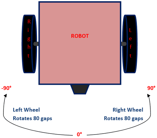
When the robot is initialized the angle it’s facing is considered as 0°. From there it rotates the left the angle is incremented in negative and if it rotates right the angel is incremented in positive. For understanding let’s consider the range of -90 to +90 as shown in the figure. In such an arrangement since both the wheels are of the same diameter, if any one of the wheel makes a complete rotation the bot we turn at an angle of 90°.
For instance if the Left wheel makes one complete rotation (80 interrupts) then the bot will turn 90° towards the left and similarly if the Right wheel makes one complete rotation (80 interrupts) then the bot will turn -90° towards the right. Now we know that if the Arduino detects 80 interrupts on one wheel then the bot has turned by 90° and based on which wheel we can tell if the bot has turned by positive (right) or negative (left). So the left and right angle can be calculated using the below formulae
int angle_left = (left_intr % 360) * (90/80) ;
int angle_right = (right_intr % 360) * (90/80) ;
Where 90 is the angle covered when making an interrupt of 80. The resulting value is multiplied number interrupts. We have also used a modulus of 360 so that the resulting value never exceeds 36. Once we have calculated both the left and right angle the effective angle at which the bot is facing can be simply obtained by subtracting the left angle form the right angle.
angle = angle_right - angle_left;
Arduino Robot Code
The complete Arduino code for this speed and angle measurement robot can be found at the end of this page. The aim of the program is to calculate the speed, distance and angle of the bot using the above logics and display it on the LCD screen. Apart from that it should provide an option to control the bot using the Joystick.
We start the program by defining the Digital I/O pins for the two motors. Do note that we also have to control the sped of the motor and hence we have to use the PWM pins on Arduino to control the motors. Here we have used the pin 8,9,10 and 11.
#define LM_pos 9       // left motor
#define LM_neg 8       // left motor
#define RM_pos 10       // right motor
#define RM_neg 11       // right motor
#define joyX A2
#define joyY A3
To measure the speed and distance covered we need to know the radius of the wheel, measure the value and enter it in meters as shown below. For my bot the radius was 0.033 meters but it could differ for you based on your bot.
float radius_of_wheel = 0.033; //Measure the radius of your wheel and enter it here in cm
Inside the setup function, we initialize all value to be zero and then display an Intro Text on the LCD. We have also initialized the serial monitor for debugging purpose. Then we have mentioned that the speed sensors H206 are connected to pin 2 and 3 as external interrupts. That is where ever the interrupt is detected the ISR function Left_ISR and Right_ISR will be executed accordingly.
void setup()
{
  rotation = rpm = pevtime = 0; //Initialize all variable to zero
  Serial.begin(9600);
  lcd.begin(16, 2); //Initialise 16*2 LCD
  lcd.print("Bot Monitor"); //Intro Message line 1
  lcd.setCursor(0, 1);
  lcd.print("-CircuitDigest "); //Intro Message line 2
  delay(2000);
  lcd.clear();
  lcd.print("Lt:     Rt:    ");
  lcd.setCursor(0, 1);
  lcd.print("S:     D:  A:   ");

  pinMode(LM_pos, OUTPUT);
  pinMode(LM_neg, OUTPUT);

  pinMode(RM_pos, OUTPUT);
  pinMode(RM_neg, OUTPUT);

  digitalWrite(LM_neg, LOW);
  digitalWrite(RM_neg, LOW);

  attachInterrupt(digitalPinToInterrupt(2), Left_ISR, CHANGE); //Left_ISR is called when left wheel sensor is triggered
  attachInterrupt(digitalPinToInterrupt(3), Right_ISR, CHANGE);//Right_ISR is called when right wheel sensor is triggered
}
Inside the Left_ISR routine, we simply increment a variable called left_intr which will be later used in measuring the angle of the bot. Inside the Right_ISR we do the same thing but then additionally we also calculate the speed here. The variable rotation is incremented for every interrupt and then the above logic is used to calculate the speed.
void Left_ISR()
{
  left_intr++;delay(10);
}


void Right_ISR()
{
  right_intr++; delay(10);

  rotation++;
  dtime=millis();
  if(rotation>=40)
  {
    timetaken = millis()-pevtime; //timetaken in millisec
    rpm=(1000/timetaken)*60;    //formulae to calculate rpm
    pevtime = millis();
    rotation=0;
  }
}
Inside the main infinite loop function we monitor the values of X and Y from the joystick. Based on the value if joystick is moved we control the bot accordingly. The speed of the bot depends on how far the joystick is pushed.
int xValue = analogRead(joyX);
 int yValue = analogRead(joyY);

int acceleration = map (xValue, 500, 0, 0, 200);

if (xValue<500)
{
analogWrite(LM_pos, acceleration);
analogWrite(RM_pos, acceleration);
}

else
{
analogWrite(LM_pos, 0);
analogWrite(RM_pos, 0);
}

if (yValue>550)
analogWrite(RM_pos, 80);

if (yValue<500)
analogWrite(LM_pos, 100);
This will help the user to move the bot and check if the values obtained are as expected. Finally we can calculate the speed, distance and angle of the bot using the above logics and display it on the LCD using the below code.
v = radius_of_wheel * rpm * 0.104; //0.033 is the radius of the wheel in meter
 distance = (2*3.141*radius_of_wheel) * (left_intr/40);
 int angle_left = (left_intr % 360) * (90/80) ;
 int angle_right = (right_intr % 360) * (90/80) ;
 angle = angle_right - angle_left;

lcd.setCursor(3, 0); lcd.print("    "); lcd.setCursor(3, 0); lcd.print(left_intr);
lcd.setCursor(11, 0); lcd.print("    "); lcd.setCursor(11, 0);lcd.print(right_intr);
lcd.setCursor(2, 1); lcd.print("  "); lcd.setCursor(2, 1);lcd.print(v);
lcd.setCursor(9, 1); lcd.print("  "); lcd.setCursor(9, 1);lcd.print(distance);
lcd.setCursor(13, 1); lcd.print("   "); lcd.setCursor(13, 1);lcd.print(angle);
Testing the Arduino Robot for measuring Distance, Speed and Angle
Once your hardware is ready upload the code into your Arduino and use the joystick to move your bot. the speed of the bot, distance covered by it and the angle will be displayed in the LCD as shown below.
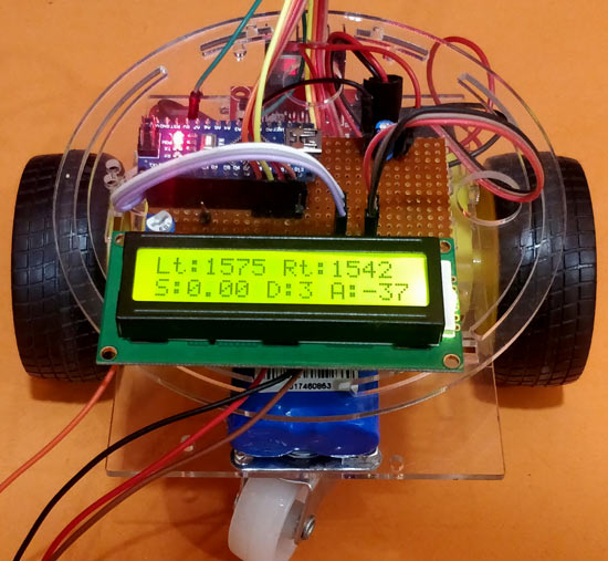
On the LCD the term Lt and Rt represents Left Interrupt Count and Right Interrupt count respectively. You can find these values getting incremented for every gap detect by the sensor. The tem S indicates the Speed of the bot in m/sec and the term D indicates Distance covered in meters. The Angle of the bot is displayed at the end where 0° is for straight and it goes negative for anti-clockwise rotation and positive for clockwise rotation.
You can also watch the video at the end of this page to understand how the bot works. Hope you understood the project and enjoyed building it. If you have any concerns leave them in the comment section and I will try by best in responding back. You can also use forums for quick technical help.
/*
* Arduino Vehicle Speed, Distance and angle calculator
*/
/*-------defining pins------*/
#define LM_pos 9 // left motor
#define LM_neg 8 // left motor
#define RM_pos 10 // right motor
#define RM_neg 11 // right motor
#define joyX A2
#define joyY A3
#include <LiquidCrystal.h>
const int rs = 14, en = 15, d4 = 4, d5 = 5, d6 = 6, d7 = 7; //Mention the pin number for LCD connection
LiquidCrystal lcd(rs, en, d4, d5, d6, d7);
int left_intr = 0;
int right_intr = 0;
int angle = 0;
/*Hardware details*/
float radius_of_wheel = 0.033; //Measure the radius of your wheel and enter it here in cm
volatile byte rotation; // variale for interrupt fun must be volatile
float timetaken,rpm,dtime;
float v;
int distance;
unsigned long pevtime;
void setup()
{
rotation = rpm = pevtime = 0; //Initialize all variable to zero
Serial.begin(9600);
lcd.begin(16, 2); //Initialise 16*2 LCD
lcd.print("Vechile Monitor"); //Intro Message line 1
lcd.setCursor(0, 1);
lcd.print("-CircuitDigest "); //Intro Message line 2
delay(2000);
lcd.clear();
lcd.print("Lt: Rt: ");
lcd.setCursor(0, 1);
lcd.print("S: D: A: ");
pinMode(LM_pos, OUTPUT);
pinMode(LM_neg, OUTPUT);
pinMode(RM_pos, OUTPUT);
pinMode(RM_neg, OUTPUT);
digitalWrite(LM_neg, LOW);
digitalWrite(RM_neg, LOW);
attachInterrupt(digitalPinToInterrupt(2), Left_ISR, CHANGE); //Left_ISR is called when left wheel sensor is triggered
attachInterrupt(digitalPinToInterrupt(3), Right_ISR, CHANGE);//Right_ISR is called when right wheel sensor is triggered
}
void loop()
{
int xValue = analogRead(joyX);
int yValue = analogRead(joyY);
int acceleration = map (xValue, 500, 0, 0, 200);
if (xValue<500)
{
analogWrite(LM_pos, acceleration);
analogWrite(RM_pos, acceleration);
}
else
{
analogWrite(LM_pos, 0);
analogWrite(RM_pos, 0);
}
if (yValue>550)
analogWrite(RM_pos, 80);
if (yValue<500)
analogWrite(LM_pos, 100);
/*To drop to zero if vehicle stopped*/
if(millis()-dtime>500) //no inetrrupt found for 500ms
{
rpm= v = 0; // make rpm and velocity as zero
dtime=millis();
}
v = radius_of_wheel * rpm * 0.104; //0.033 is the radius of the wheel in meter
distance = (2*3.141*radius_of_wheel) * (left_intr/40);
int angle_left = (left_intr % 360) * (90/80) ;
int angle_right = (right_intr % 360) * (90/80) ;
angle = angle_right - angle_left;
lcd.setCursor(3, 0); lcd.print(" "); lcd.setCursor(3, 0); lcd.print(left_intr);
lcd.setCursor(11, 0); lcd.print(" "); lcd.setCursor(11, 0);lcd.print(right_intr);
lcd.setCursor(2, 1); lcd.print(" "); lcd.setCursor(2, 1);lcd.print(v);
lcd.setCursor(9, 1); lcd.print(" "); lcd.setCursor(9, 1);lcd.print(distance);
lcd.setCursor(13, 1); lcd.print(" "); lcd.setCursor(13, 1);lcd.print(angle);
delay(100);
}
void Left_ISR()
{
left_intr++;delay(10);
}
void Right_ISR()
{
right_intr++; delay(10);
rotation++;
dtime=millis();
if(rotation>=40)
{
timetaken = millis()-pevtime; //timetaken in millisec
rpm=(1000/timetaken)*60; //formulae to calculate rpm
pevtime = millis();
rotation=0;
}
}
Comments
As I turn on supply ,one
As I turn on supply ,one motor is rotating continuously and not stopping till I turn off supply
most likely the problem is
most likely the problem is with ur connections
might be, can't i expect
might be, can't i expect trouble by code??
Correct calculation of angular velocity
When you do "rpm = (1000 / timetaken) * 60", you are actually writing "angular frequency" and not angular velocity. To calculate the angular velocity correctly you should write "rpm = 2 * π * ((1000 / timetaken) * 60)".



I just did as you explained in this article ,but I'm not getting result,and only one motor is rotating .can ik where it could go wrong .
Thanks for replying..