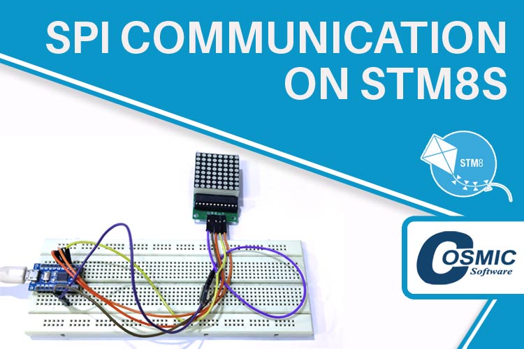
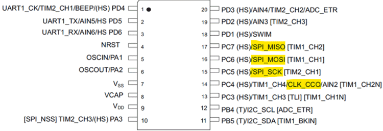
In this tutorial, we will learn about the implementation of the Serial Parallel Interface (SPI) Communication on the STM8S103F3P6 board using an 8x8 Led matrix display module as the SPI device. There are 4 GPIO pins that we will be using to perform the SPI communication as shown in the image below. So, let’s see what components will be required to perform the SPI communication on STM8S board. You can check our tutorials on the STM8S Microcontroller where we have discussed on How to setup the Cosmic C compiler and we have covered the PWM, ADC, UART and I2C with the STM8S103F3P6 development board.
Components Required
We will require the following components to perform the I2C communication on STM8S with MLX90614 I2C sensor.
- STM8S103F3P6 Development board
- ST-Link V2 programmer
- 8x8 MAX7219 Led Matrix Display Module.
- Connecting wires
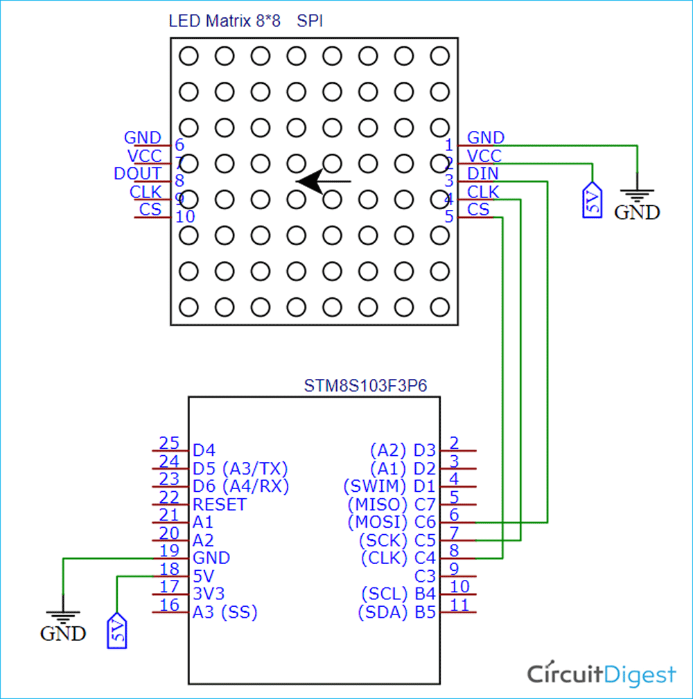
Circuit Diagram to Interface the Dot Matrix Display Module with STM8S Using SPI
The following schematic represents the connections diagram of the MAX719 Dot Matrix Display Module with the STM8S103F3P6 development board. I have connected the DIN pin of the module with the SDA (PB5) and SCL(PB4) pin of the STM8S103F3P6 board. I have also provided a 5V power supply to both the sensor and the LCD. Please note carefully that we need to power the STM8S103F3P6 board with an USB connector so that the board gives a proper 5V power supply to both the sensor and the LCD.
SPI on STM8S103F3P6
Before getting started with the SPI communication on the STM8S, you need to make sure that you have the basic understanding on how the SPI communication works. We have covered the SPI communication with different types of microcontrollers so far. So, I am not going to discuss about the theory part of the SPI communication. You need to download the complete code files from our GITHUB repository of the STM8S tutorial series. Go to the “T8_SPI_Communication_on_STM8S_using_Cosmic_C_Compiler” folder which can be found in the downloaded repository. This folder contains two subfolders viz. “inc” and “src”. We are going to use the Cosmic C compiler along with the SPL libraries. I hope you have gone through our first tutorial on STM8S where we have discussed on how to setup the project workspace. Once you have done the setup of your project workspace, you should have the following header files under the “Include Files” folder that I have marked with red circle in the below image. In the first tutorial of the STM8S, we have already discussed on how to add the include files (can be found in the “inc” folder) and the source files (can be found in the “src” folder).
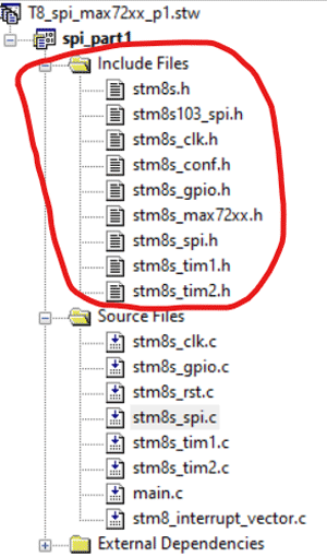
Now, let’s see what is inside the libraries. I have created two important libraries to ease the SPI communication on the STM8S. i.e. “stm8s103_spi.h” and “stm8s_max72xx.h”. You might be wondering about the other header files in the picture. You can refer to the “STM8S Standard Peripherals Library” manual. Now, let’s get into the coding part.
Inside the stm8s103_spi.h header file:
At the beginning of the stm8s103_spi.h file, we have included the “STM8S.h” header file. The “STM8S.h” file contains the definition of the “stm8s_spi.h” header file and the board configuration of the STM8S development boards. The predefined functions for the SPI communication can be found in the “stm8s_spi.h” file. Instead of discussing each of and every function in the stm8s_spi.h header file, we are going to discuss the important functions which are being used in our “stm8s103_spi.h” header file. In the “stm8s103_spi.h”, the header file has three functions for the SPI communication. Let’s discuss each functions one by one.
void delay_ms(int ms) //Function Definition
{
int i =0 ;
int j=0;
for (i=0; i<=ms; i++)
{
for (j=0; j<120; j++) // Nop = Fosc/4
_asm("nop"); //Perform no operation
}
}
The function “delay_ms()” that is mentioned above is used to provide delay in milliseconds within a task. You can find two nested for loop containing another function “_asm(“nop”)” inside the delay_ms() function. The _asm(“nop”) can be used to instruct the microcontroller not to perform any operation. This delay_ms() function can take one parameter as integer that is representing the delay in milliseconds.
void SPI_setup(void)
{
     SPI_DeInit();
     SPI_Init(SPI_FIRSTBIT_MSB,
              SPI_BAUDRATEPRESCALER_2,
              SPI_MODE_MASTER,
              SPI_CLOCKPOLARITY_HIGH,
              SPI_CLOCKPHASE_1EDGE,
              SPI_DATADIRECTION_1LINE_TX,
              SPI_NSS_SOFT,
              0x00);
     SPI_Cmd(ENABLE);
}
The next function “SPI_setup(void)” that is mentioned above is a non-returnable function and can be used to initiate the SPI communication. This function has the important functions for the SPI communication on the STM8S. Before discussing about this function, let me inform you that this function can be found in the stm8s_spi.h header file. You can simply right click on each functions and then you need to click the “Go to Definition” option which can be found inside the popup after you press the right click on the function. You can refer the image below.
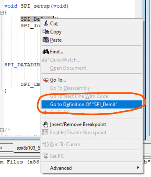
The SPI_DeInit() function can be used to stop any previously started SPI communication on the board. The SPI_Init() function is used to start the SPI communication in between the Board and the Slave. This initialize function has some parameters to take care of. You can follow the same method as mentioned above to go to the definitions of each of the parameters. We should be thanking the creator of the “stm8s_spi.h” header file because they have mentioned every detail in the file as comments. I think you will easily understand each of the parameters used in these functions by reading those comments. We can enable or disable the SPI peripheral by using the SPI_Cmd() function.
void SPI_write(unsigned char slave_address, unsigned char value)
{
    while(SPI_GetFlagStatus(SPI_FLAG_BSY));
    GPIO_WriteLow(CS_port, CS_pin);
    SPI_SendData(slave_address);
    while(!SPI_GetFlagStatus(SPI_FLAG_TXE));
    SPI_SendData(value);
    while(!SPI_GetFlagStatus(SPI_FLAG_TXE));
    GPIO_WriteHigh(CS_port, CS_pin);
}
The SPi_write() function can be used to write the data on the targeted register. Firstly, we need to check if the SPI status register is free or not. We can use the SPI_GetFlagStatus(SPI_FLAG_BSY) function under a while loop to check the status of the SPI communication. The “GPIO_WriteLow(ChipSelect_port, ChipSelect_pin)” function is used to send a ‘0’ signal to the chip select pin that is defined by using the “ChipSelect_port” and “ChipSelect_pin” at the starting of the header file. Then the “SPI_SendData(slave_address)” is used to send the slave address where the “slave_address” parameter contains the address of the targeted register of the slave device. Then we need to wait until the transmit buffer will empty. Then we will send the value by using the “SPI_SendData(value)”. Then we need to check the status of the transmit buffer again and we need to wait until it is empty. Now, we can set the chip select pin to HIGH by using the “GPIO_WriteHigh(ChipSelect_port, ChipSelect_pin)”.
There are some errors that you may face while performing the SPI on the STM8S. I have mentioned the errors that I faced while I was implementing this. i.e.
- “while(!SPI_GetFlagStatus(SPI_FLAG_TXE))” loop will never break. That means the transmit buffer is not empty. You can check the address bit that you are sending by using the “SPI_SendData()” function. Or you can check your wiring setup, if all the wires are properly connected or not.
Inside the stm8s_max72xx.h header file:
The “stm8s_max7xx.h” header file has some functions that can be used while interfacing the 8x8 MAX72xx Led Matrix Display board with the STM8S using SPI communication. At the starting of this file, I have defined some macros for the device registers individually. These addresses can be found from the datasheet of the MAX72xx IC.
#define decode_mode_reg        0x09
#define intensity_reg                    0x0A
#define scan_limit_reg                                 0x0B
#define shutdown_reg                                0x0C
#define display_test_reg              0x0F
#define shutdown_cmd               0x00
#define run_cmd                           0x01
#define no_test_cmd                   0x00
#define test_cmd                          0x01
Then the “alphabets[26]” is the char array to store the 26 alphabets. The “alpha_char[26][8]” is a Two Dimensional (2D) array which contains the eight 8-bit addresses of every alphabets for a 8x8 Led Matrix. For example, let’s look into the 0th index of the “alpha_char”, we have eight 8-bit hex data. This hex data represents the alphabet “A” in the 8x8 matrix format.
const char alphabets[26]= "ABCDEFGHIJKLMNOPQRSTUVWXYZ";
const uint8_t alpha_char[26][8] = {{0x0, 0xfc, 0xfe, 0x27, 0x27, 0xfe, 0xfc, 0x0},
{0x0, 0xfe, 0xfe, 0x92, 0x92, 0xfe, 0x6c, 0x0},
{0x0, 0x7e, 0xff, 0xc3, 0xc3, 0xe7, 0x66, 0x0},
{0x0, 0xff, 0xff, 0xc3, 0xc3, 0xff, 0x7e, 0x0},
{0x0, 0xfe, 0xfe, 0x92, 0xba, 0x82, 0xc6, 0x0},
{0x82, 0xfe, 0xfe, 0x92, 0x3a, 0x2, 0x6, 0x0},
{0x0, 0x7e, 0xff, 0xc3, 0xd3, 0xf7, 0x76, 0x0},
{0x0, 0xfe, 0xfe, 0x30, 0x30, 0xfe, 0xfe, 0x0},
{0x0, 0xc6, 0xc6, 0xfe, 0xfe, 0xc6, 0xc6, 0x0},
{0x0, 0x30, 0x70, 0x63, 0x63, 0x7f, 0x3f, 0x3},
{0x0, 0xff, 0xff, 0x18, 0x3c, 0x6e, 0xc7, 0x0},
{0x0, 0x81, 0xff, 0xff, 0x81, 0x80, 0xe0, 0x0},
{0x0, 0xfe, 0xfe, 0x1c, 0x38, 0x1c, 0xfe, 0xfe},
{0x4e, 0xc6, 0xe6, 0xf6, 0xde, 0xce, 0xc6, 0xc6},
{0x4f, 0x38, 0x6c, 0xc6, 0xc6, 0xc6, 0x6c, 0x38},
{0x50, 0xfc, 0x66, 0x66, 0x7c, 0x60, 0x60, 0xf0},
{0x51, 0x78, 0xcc, 0xcc, 0xcc, 0xdc, 0x78, 0x1c},
{0x0, 0xff, 0xff, 0x33, 0x33, 0xff, 0xee, 0xc0},
{0x0, 0xce, 0xdf, 0xdb, 0xdb, 0xfb, 0x73, 0x0},
{0x0, 0x7, 0x83, 0xff, 0xff, 0x83, 0x7, 0x0},
{0x0, 0x7f, 0xff, 0xc0, 0xc0, 0xff, 0x7f, 0x0},
{0x56, 0xcc, 0xcc, 0xcc, 0xcc, 0xcc, 0x78, 0x30},
{0x57, 0xc6, 0xc6, 0xc6, 0xd6, 0xfe, 0xee, 0xc6},
{0x58, 0xc6, 0xc6, 0x6c, 0x38, 0x38, 0x6c, 0xc6},
{0x59, 0xcc, 0xcc, 0xcc, 0x78, 0x30, 0x30, 0x78},
{0x7f, 0x7f, 0x61, 0x31, 0x98, 0x8c, 0xfe, 0xfe}
};
Then we have a “string_len()” function to get the length of a string. I made a MAX7219_init() function to initialize the MAX7219 LED matrix as a Slave device. In this function, you can see that I have initialized the “ChipSelect_port” and “ChipSelect_pin” in “GPIO_MODE_OUT_PP_HIGH_FAST” mode. We need to follow the datasheet to initialize the MAX7219 by using that register commands. I called the “SPI_write()” function to write the data in the resisters that I have defined at the top of the header file.
void MAX7219_init(void)
{
    GPIO_Init(ChipSelect_port, ChipSelect_pin, GPIO_MODE_OUT_PP_HIGH_FAST);
    SPI_write(shutdown_reg, run_cmd);
    SPI_write(decode_mode_reg, 0x00);
    SPI_write(scan_limit_reg, 0x07);
    SPI_write(intensity_reg, 0x04);
    SPI_write(display_test_reg, test_cmd);
    delay_ms(10);
    SPI_write(display_test_reg, no_test_cmd);
}
The “display_clear(void)” function that is mentioned below is used to clear the LED matrix. I used an eight 8-bit 0’s in the “zeros_clr[8]” array. Then I used every single bit of this array in a for loop to set every led of the 8x8 LED matrix display into ‘0’ or ‘LOW’.
void display_clear(void) {
                    unsigned char zeros_clr[8] = {0x00, 0x00, 0x00, 0x00, 0x00, 0x00, 0x00, 0x00};
 unsigned char j = 0x00;
                for(j = 0; j < sizeof(zeros_clr); j++)
                {
                                                SPI_write((1 + j), zeros_clr [j]);
                                                delay_ms(100);
                }
}
The “display_char(int alphabet_sequence)” can be used to display a character in on the led matrix display board. We need to provide the alphabet index of the “alpha_char[][]” array. Inside the function we have the “SPI_write()”. This time we are providing the register value of the row and the column of the Led Matrix to write the data on the particular led.
void display_char(int alphabet_sequence)
{
                  unsigned int i;
                                for(i=0; i<8; i++){
                SPI_write((i+1), alpha_char[alphabet_sequence][i]);
                                                             delay_ms(100);
                                }
}
The “display_string()” can be used to display a string. It is a simple program where I used a character comparison to compare every character of the input string with every character of the “alphabets”. I recorded the index of for the “alphabets” in “pos” variable for every character in the input string and passing this index into the “display_char()”.
void display_string(const char string[]){
    unsigned char j,pos;
    int input_string_length  = string_len(string);
                                int alphabets_length  = string_len(alphabets);
                for(j=0; j<input_string_length; j++){
                pos = 0;
                while(alphabets[pos]!='\0'){
                if(string[j] == alphabets[pos])
                                display_char(pos);
                pos++;
                delay_ms(500);
                }
}
}
Inside the main.c file:
Now, we have the main.c file to be discussed. In the main.c file we have three functions. i.e. main(), clock_setup() and GPIO_setup(). In the clock_setup() function I have used the CLK_DeInit() function to stop any previously started clock inside the microcontroller. You can easily get a detailed instructions of every function and parameter used here. You need to use the “Go to Definition” method that I have discussed before. In the GPIO_setup(), I used the GPIO_DeInit() function to de-initialized the port C. And then I initialized the Pin 5 and Pin 6 of the Port C. by using the GPIO_Init() function.
void clock_setup(void)
{
     CLK_DeInit();
     CLK_HSICmd(ENABLE);
     while(CLK_GetFlagStatus(CLK_FLAG_HSIRDY) == FALSE);
     CLK_ClockSwitchCmd(ENABLE);
     CLK_HSIPrescalerConfig(CLK_PRESCALER_HSIDIV1);
     CLK_SYSCLKConfig(CLK_PRESCALER_CPUDIV1);
     CLK_ClockSwitchConfig(CLK_SWITCHMODE_AUTO, CLK_SOURCE_HSI,
     DISABLE, CLK_CURRENTCLOCKSTATE_ENABLE);
     CLK_PeripheralClockConfig(CLK_PERIPHERAL_SPI, ENABLE);
}
void GPIO_setup(void)
{
     GPIO_DeInit(GPIOC);
     GPIO_Init(GPIOC, ((GPIO_Pin_TypeDef)GPIO_PIN_5 | GPIO_PIN_6),
               GPIO_MODE_OUT_PP_HIGH_FAST);
}
In the main() function, I have called the four functions that we discussed so far. These functions can be used in the same sequence to established the SPI communication on the STM8S. Then we have the “display_clear()” function to clear the display at the start-up. Then I called the “display_char()” with a parameter ‘0’ to display the alphabet “A”. In the “while()” loop I used the “display_string()” followed by the “display_clear()” function to display a string. In my case, I am using “CIRCUITDIGEST” as string to display on the Led Matrix Display. It will display this string in every 2 seconds of interval.
So, finally we have done the SPI Communication on the STM8S103F3P6 development board. You can refer to the video below to see the practical demonstration. I have explained the code in the following video.
#include "STM8S.h"
#include "stm8s103_SPI.h"
#include "stm8s_max72xx.h"
void clock_setup(void);
void GPIO_setup(void);
void main()
{
const char input_string2[] = "CIRCUITDIGEST";
clock_setup();
GPIO_setup();
SPI_setup();
MAX7219_init();
display_clear(); //Clearing the display
delay_ms(1000);
display_char(0); // Displaying the alphabet "A"
delay_ms(4000);
while(TRUE)
{
display_clear(); //Clearing the Display
display_string(input_string2); //Displaying a String
delay_ms(2000);
};
}
void clock_setup(void)
{
CLK_DeInit();
CLK_HSICmd(ENABLE);
while(CLK_GetFlagStatus(CLK_FLAG_HSIRDY) == FALSE);
CLK_ClockSwitchCmd(ENABLE);
CLK_HSIPrescalerConfig(CLK_PRESCALER_HSIDIV1);
CLK_SYSCLKConfig(CLK_PRESCALER_CPUDIV1);
CLK_ClockSwitchConfig(CLK_SWITCHMODE_AUTO, CLK_SOURCE_HSI,
DISABLE, CLK_CURRENTCLOCKSTATE_ENABLE);
CLK_PeripheralClockConfig(CLK_PERIPHERAL_SPI, ENABLE);
}
void GPIO_setup(void)
{
GPIO_DeInit(GPIOC);
GPIO_Init(GPIOC, ((GPIO_Pin_TypeDef)GPIO_PIN_5 | GPIO_PIN_6),
GPIO_MODE_OUT_PP_HIGH_FAST);
}

