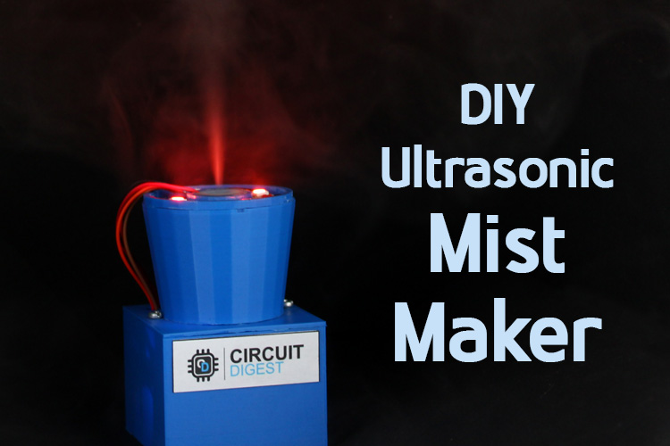
Fog and Lights is a combination that has the potential to amuse adults and kids alike, so we decided to venture into the realm of ultrasonic mist maker modules and got our hands on one without much trouble. When we first tested a tiny-looking ultrasonic humidifier module, we were intrigued by the capabilities this small module possessed. Resonating at a frequency of 1.7 MHz, it produces mechanical vibrations, enough to catapult water droplets into the air in the form of vapor. Adding lights and musical control was the next step, and what else can we think of other than Neopixels when it comes to a light show? We have previously used Neopixel led in many projects like Arduino Mood Light, Christmas tree light, Reactive Bluetooth speakers, etc, you can check them out if you are interested.
In this article, we will discuss how to make an ultrasonic-mist light and sound show using an Ultrasonic Humidifier Module.
Components Required
- ESP8266 - ESP01 Module
- USB To TTL Converter Module
- Ultrasonic Humidifier Module
- WSB2812 IC. 5 Units.
- TP4056 Module
- 3.7V 700mAh Li-Po Battery
- LDR
- IRF540N MOSFET
How does ultrasonic mist maker work?
While the Ultrasonic Humidifier Module is the prime focus of the project as it is the unit that produces the mist. We have previously used this ultrasonic humidifier to build a portable humidifier using arduino that can control the humidity of the room based on present temperature and humidity. The main task of controlling the operation of the device lies with the ESP01 Module, which is also known commonly by the name ESP8266. We have built many ESP8266 projects previously, you can also check them out if you are interested.
The ESP01 is running an open-source firmware called the ESPixelStick firmware. This firmware can be used to easily control the WS2812 LEDs daisy-chained and connected to a single GPIO of the ESP01. We can control data to the ESP01 over Wifi either using the MQTTT or using any software that supports the E1.31 protocol. In this project, we will be using a simple open-source software called VixenLights which is a great GUI Tool for syncing light and sound shows over music.
The VixenLights software allows us to control various outputs as a time sequence, this sequence data is sent by the software to the ESP-01 over Wifi. The ESP Running the ESPixelStick firmware takes this data and pushes it onto the WS2812B LEDs daisy chained on a single pin.
Controlling LEDs with the ESPixelStick firmware becomes really easy but we still have to control the humidifier module on the same platform.
To achieve this functionality without diving deep into the firmware we make a hardware workaround. By placing an LDR right in front of one of the WS2812B LEDs and enclosing these two components in a black heat shrink, we can make a practical opto-isolator that can now be used to drive a MOSFET that can in turn control our UltraSonic Humidifier Module.
Since an ESP01 runs on 3.3V, A 3.7V 700mAh Li-Po Battery with a TP4056 charging module is enough to power the whole system for us.
Uploading The ESPixelStick Firmware
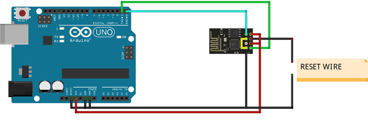
Let us begin building the project by flashing the ESP-01 with the ESPixelStick firmware. To do so, we need to communicate with the ESP01 for which we will use an Arduino UNO. You can simply bypass the onboard controller by connecting the RESET Pin on the UNO to the GND.
Now make the connections as shown below between your Arduino UNO and the ESP01. We will put the ESP01 in Flash Mode by connecting the GPIO0 to GND.
Before moving ahead, we will download the CHR340 Drivers.
We now download the latest release of the ESPixelStick firmware from their official GitHub repository under the releases section.
![]()
Select the zip file under the assets tab.
![]()
Once the file is downloaded, extract the zip file and open the folder.
Open the file “ESPSFlashTool.jar”
Enter the name of the Wifi to which you want your ESP01 to connect, in the SSID field.
Enter the password of the Wifi in the Paraphrase field.
You can leave the Hostname, Device ID, Firmware, and Platform to its default.
Select the USB Port to which your Arduino is connected.
![]()
Click on the “Build EFU” button and select any destination for the EFU file to be saved.
![]()
Before clicking on the Upload button, we will connect the Reset Pin of ESP01 to GND.
Click on the Upload button, when you see “connecting” on the console window, remove the Reset Pin of ESP01 from GND and leave it idle.
The Flashing tool will now automatically connect to your ESP module and upload the firmware. On the status console, you can see the text as “Programming Complete”.
![]()
Once this is done, we can remove the GPIO_0 Pin Connection from GND. Simple restart the ESP by putting the reset pin jumper on GND for a second and releasing it.
Once your ESP01 boots up, it will automatically connect to the Wifi using the credentials you entered.
You can determine the IP of the ESP device by opening the command prompt and entering the command
ipconfig
You can note down the default gateway IP.
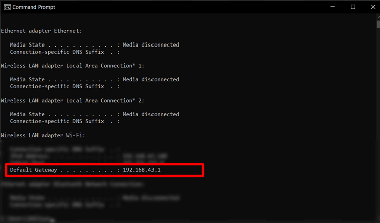
Enter this IP range in the Angry IP Scanner.
You can see the IP of the ESP from the list.
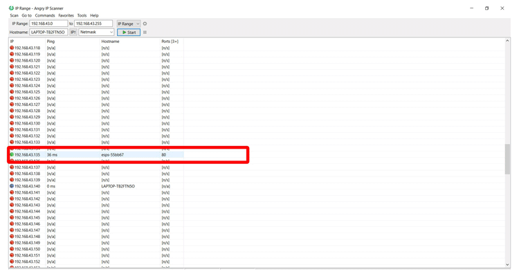
Enter this IP on a web browser to open the web interface of the ESPixelStick Firmware.
In the web interface, open the “Device Setup” tab.
![]()
You can set the following parameters and leave the rest to default values
Universe Boundary to 510
Pixel Count to 5
Pixel Type to WS2811 800kHz
Color Order to GRB
Zigzag Count to 0
Once this is done, our ESP configuration is done and we can move on to building the circuit.
DIY ESP8266 Mist Maker Circuit Diagram and Assembly
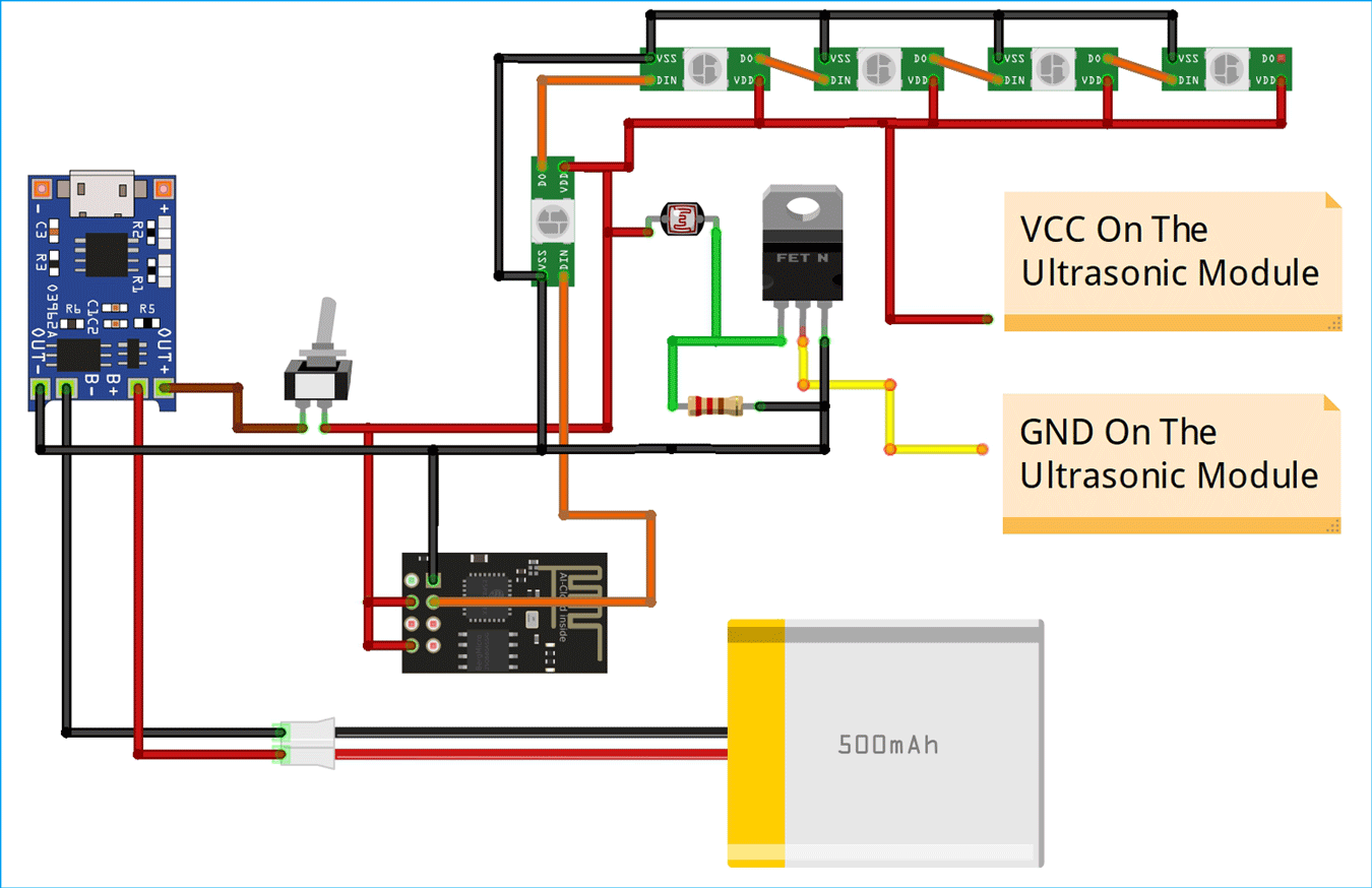
Now we can make the connections of the Humidifier circuit as per the fritzing schematic shown below.
As discussed previously, we will also be using a practical opto-isolator for the functioning of this project, the placement of the LED and LDR should be facing each other as shown below:
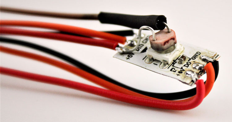
The VDD and GND Terminal of the Ultrasonic Module are connected to the Micro-USB Port on the Module PCB. Simply solder wires on these pins to directly power the module.
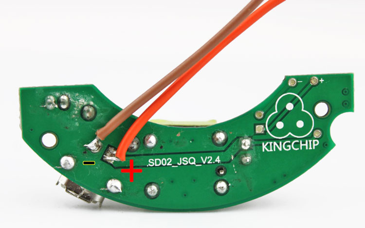
It is highly recommended to use proper heat shrinks on your solder joints to prevent any shorts.
You can 3D-Print the STL files given and follow the video shown below to complete the assembly of your device.
Software Control Setup
Our device is almost ready and all we need to do to control it is install the software “VixenLights” from its official repository. Install the latest release from the downloads page of the VixenLights website.
Open the software and click on the Setup Display button.
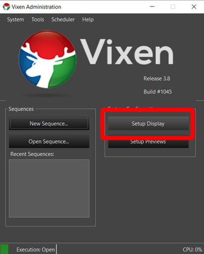
This will open the Display Setup window. Under the Elements Panel, select “Single Item” from the drop-down menu.
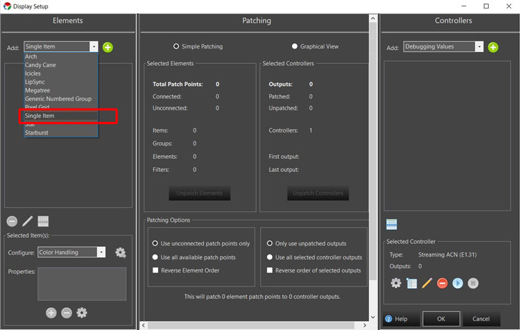
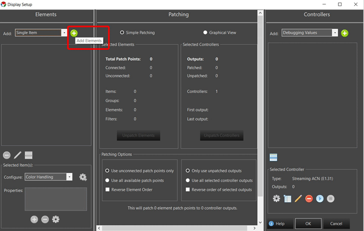
Click on “Add Elements”
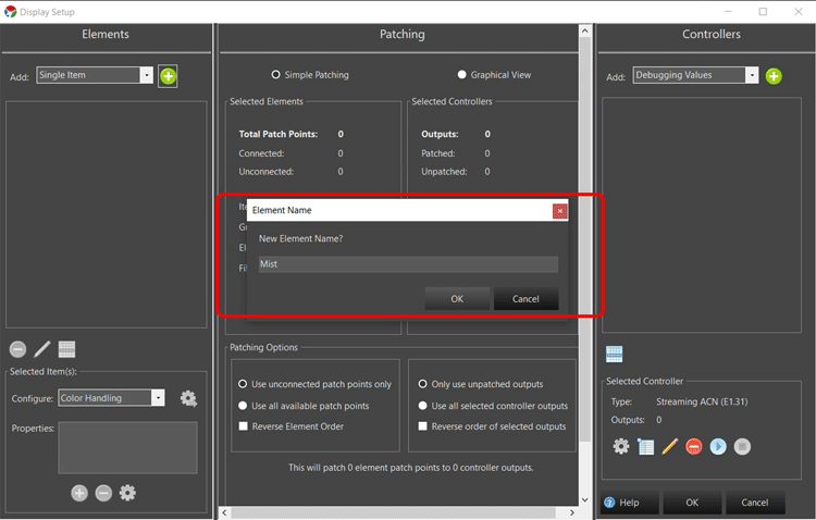
You can name this element, we have named it “Mist”, as this will control the Ultrasonic Humidifier.
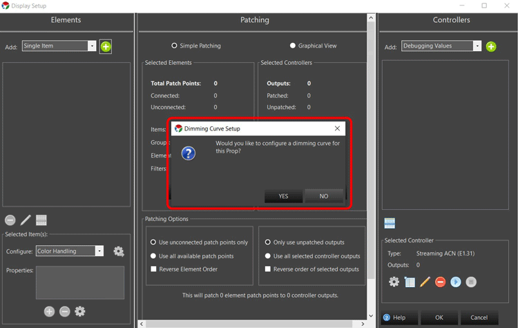
When prompted to set a dimming curve, you can simply click on NO as we will be using the defaults.
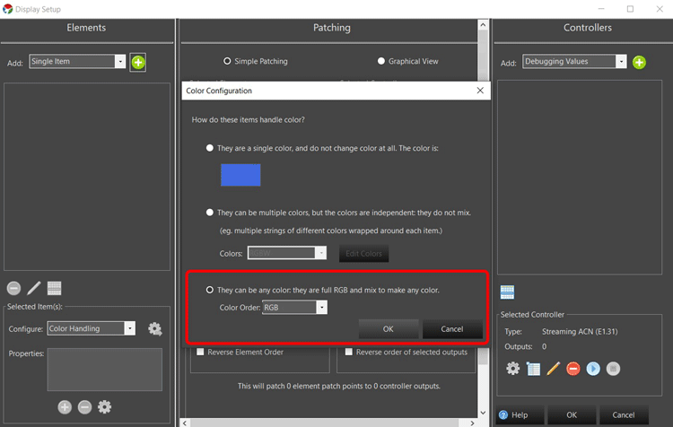
The color configuration tab will open up, make sure to select the RGB Option. And click OK.
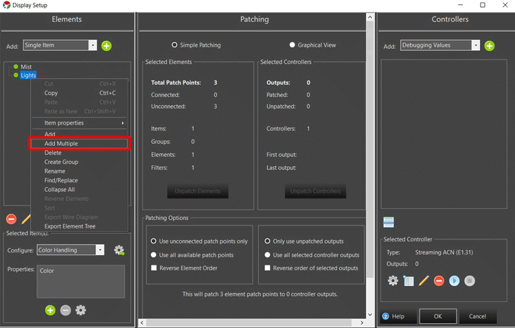
Similarly, create another element called “Lights”. Right-click on this element and then click on the Add Multiple option.
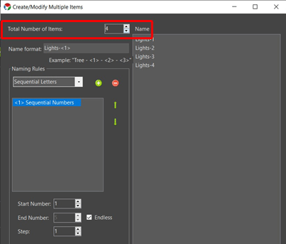
The multiple item window opens up, in the “Total Number of Items” you need to enter 4 and click OK.
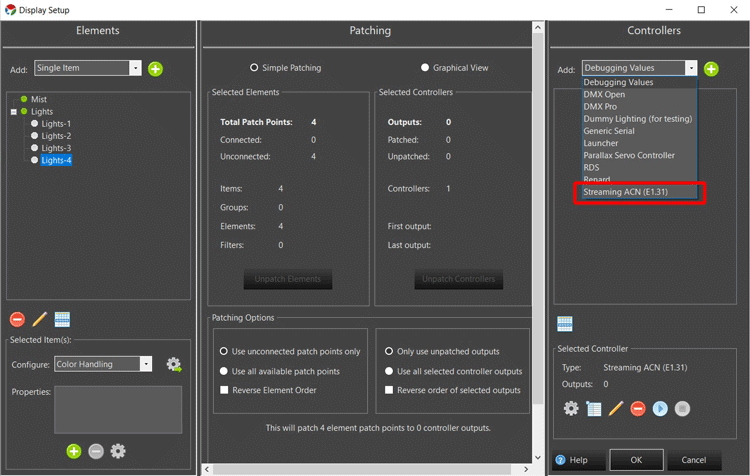
We will now add a controller for all these elements. In the controllers' panel on the right side of the window, click on the dropdown menu and select “Streaming CAN (E1.31)” and click on the Add button.
You can name the controller anything, we left it default.
In the output option, set the number of outputs to 15 and click OK.
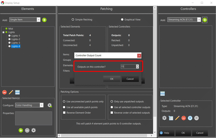
Select your controller and click on the configure button.
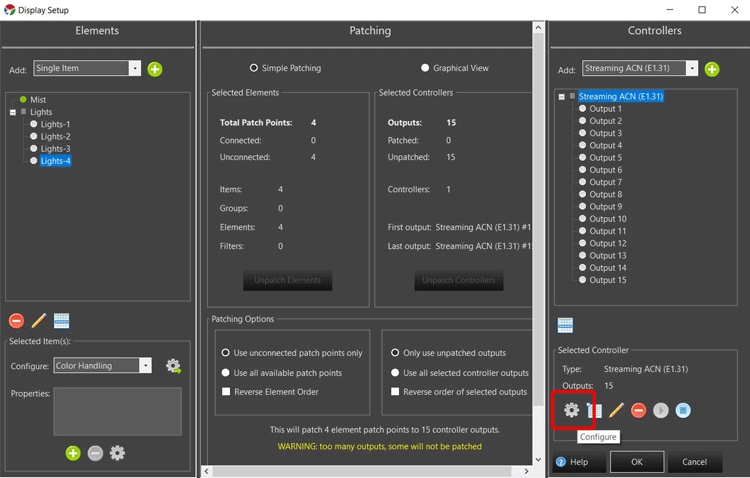
Set the size to 15.
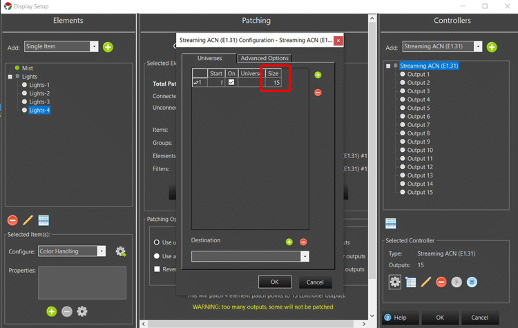
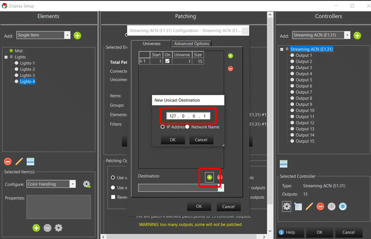
In the Destination option, click on the add button to add a new destination.
Enter the IP address of your ESP Device and click OK.
We move back to the elements panel and select the element group lights. And click on configure.
Tick the RGB color option and click OK.
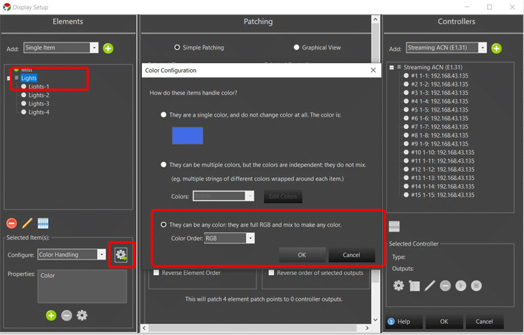
Now we simply need to patch the elements to the controllers, to do that simply select the Mist and Lights element in the elements panel and select the controller in the “Controllers” panel.
Scroll down the “Patching” Panel and click on the “Patch Elements” button.
You shall see a patching complete prompt.
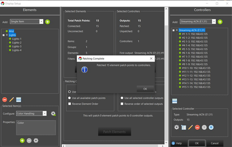
You can scroll back up and click on the “Graphical View” option to see all the elements and controllers patched together.
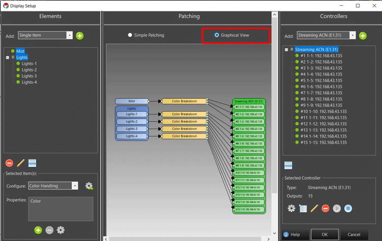
You can now click ok to exit the Display Setup.
Click on the new sequence to open the sequence editor.
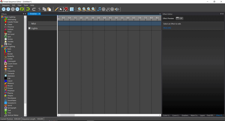
The sequence editor of VixenLights is pretty intuitive and simple to use, simply drag and drop effects from the effects panel into the main timeline, you can explore various features of the software.
When you make a sequence and press on the play button, you can see all the LEDs performing the sequence operations.
Add in music using the Associate Audio button and make a cool light and sound show.

