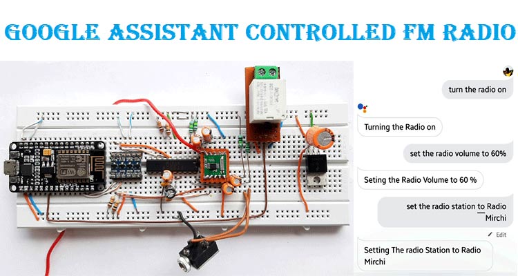
Nowadays, most of us like to listen to music, with our smartphones. But a few years back, this was not the case, at that point in time, FM radios were the first choice for listening to music, podcasts, news, and others. Nowadays nobody listens to the radio for music, news, and others, grandma and grandpa being an exception.
So, to revive the old glory of the FM radio a bit, in this project, I am going to building a voice-controlled FM radio using Google Assistance and the popular RDA5870M Superheterodyne Receiver IC.
Also, check our previous FM radio circuits:
- Arduino Based FM Radio
- Smart Phone Controlled FM Radio using Arduino
- Simple FM Transmitter Circuit
- How to Build FM Transmitter Circuit
RDA5807M IC
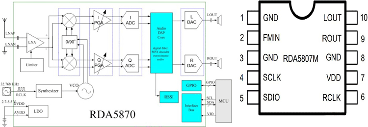
The RDA5807M is a very modern single-chip FM stereo radio tuner with a fully integrated synthesizer, IF selectivity, RDS/RBDS, and MPX decoder which supports the 50MHz to 115MHz frequency range. It's a very cheap single-chip FM receiver IC which requires very little external components to operate functionally. This IC uses the I2C interface to communicate with any master device, so all this feature makes it very suitable for portable devices.
This IC has an internal Audio Processor which is responsible for its great audio quality.
Some of the basic features include-
- Support for worldwide frequency bands
- Support for RDS/RBDS
- Digital low-IF tuner
- Fully integrated digital frequency synthesizer
- Digital auto gain control (AGC)
- Bass boost
- Directly support 32Ω resistance loading
- Integrated LDO regulator & more
You can learn more about this IC by going through this project Arduino based FM Radio using RDA5807.
IC PT2258
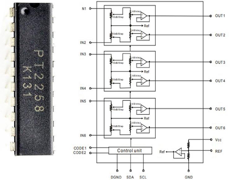
The PT2258 is an IC made to use as a 6-Channel Electronic Volume Controller, this IC uses CMOS technology specially designed for multi-channel audio-video applications.
This IC provides an I2C Control Interface with an attenuation range of 0 to -79dB at 1dB/step and comes in a 20-pin DIP or SOP package.
Some of the basics feature include-
- 6-Input and output channels (For 5.1 Home Audio Systems)
- Selectable I2C address (For Daisy-chain Application)
- High channel Separation (For Low Noise Application)
- S/N ratio of > 100dB
- Operating voltage is 5 to 9V
We previously explained about this IC in the PT2258 Digital Audio Volume Control Project. You can check that project if you want to know more about this IC.
Schematic
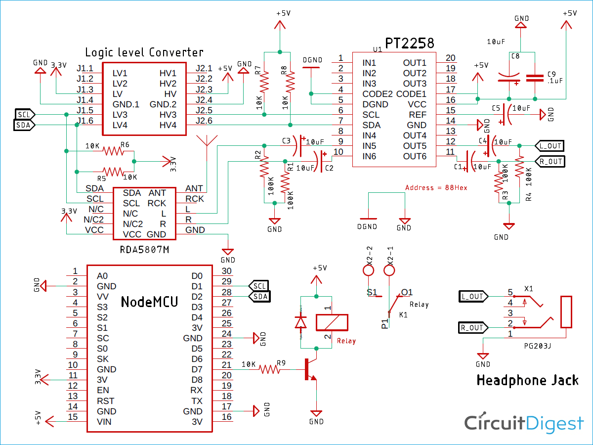
Circuit diagram for Google Assistant Controlled FM Radio is given below:
Components Required
- NodeMCU Microcontroller – 1
- PT2258 Digital Volume Controller – 1
- RDA5807 FM Radio Module – 1
- SPDT Relay 6V – 1
- 1n4007 Diode – 1
- Screw Terminal 5mmx2 – 1
- 3.5mm Headphone Jack – 1
- Logic Level Converter – 1
- 10K Resistor, 5% - 4
- 150K Resistor, 5% - 4
- 100K Resistor, 5% - 2
- 10uF Capacitor – 6
- 0.1uF Capacitor – 1
- Jumper Wire - 10
How are we Getting Data from Google Assistant?
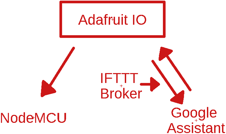
The above image gives you the basic idea of the communication process between the Google Assistant and the NodeMCU.
The Google Assistant has the authority to modify data in the Adafruit IO server to do that IFTTT with MQTT is working as a broker.
If any data change occurs on the server-side (Adafruit IO), that is reflected on the NodeMCU side. To achieve this, you need to follow the instruction given below-
Setting up an Adafruit Account for Communication
First, make an Adafruit IO account. Login to Adafruit IO with your credentials or Sign up if you don’t have an account. We previously used Adafruit IO to build Alexa controlled LED, Raspberry Pi home automation, and many other IoT based Projects.
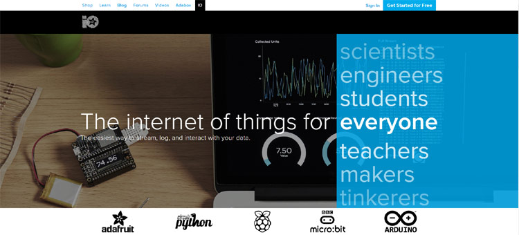
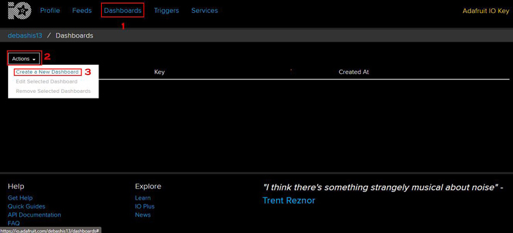
After logging in to Adafruit account,
Click on Dashboards, then click on Action > Create a New Dashboard.
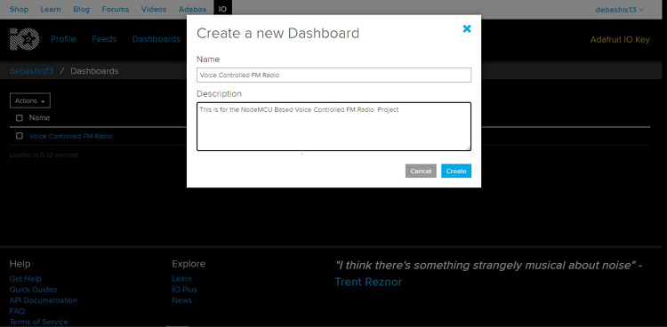
Next, we are going to add a new name & a short description of our new Dashboard.
After you've created the dashboard, you need to get the Username and the Active Key from your account as it's required in the Arduino code. You can get that by clicking on the KEY icon.

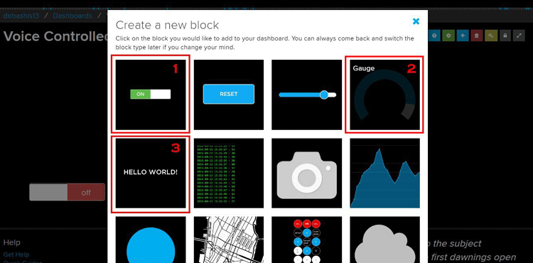
After that, make three blocks; one Toggle Block, one Gauge Block, one Text Block.
The blocks are very important, as these blocks are responsible for the communication between google assistance and the NodeMCU.
To make a block, you need to click on the + sign in the upper right-hand corner.
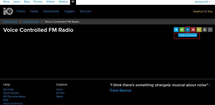
Next, we are going to make the blocks.
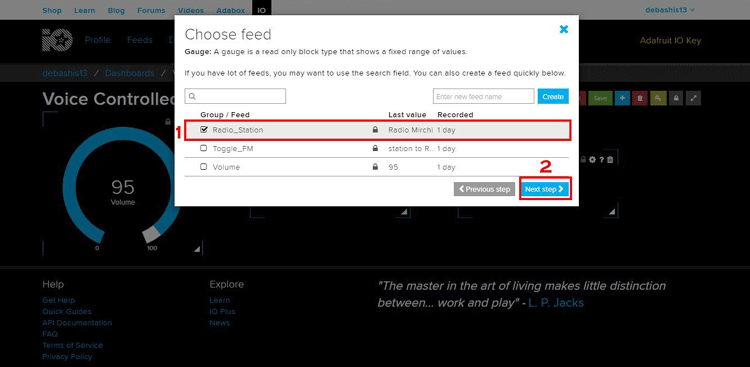
Next, You need to set up every block, for that, you need to tick on a particular block and click Next step.
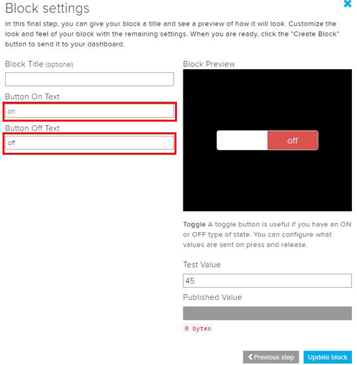
For this project, there is no need to change any settings except for the toggle button.
The text in the toggle button is in capital letters, you need to make it a small letter and update the changes.
That’s it, it's all the things you need to set up in the adafruit IO.
My final screen looks like this-

Setting up an IFTTT Broker for FM Radio
As always, Sign Up if you do not have an account or Sign In if you already have an account.
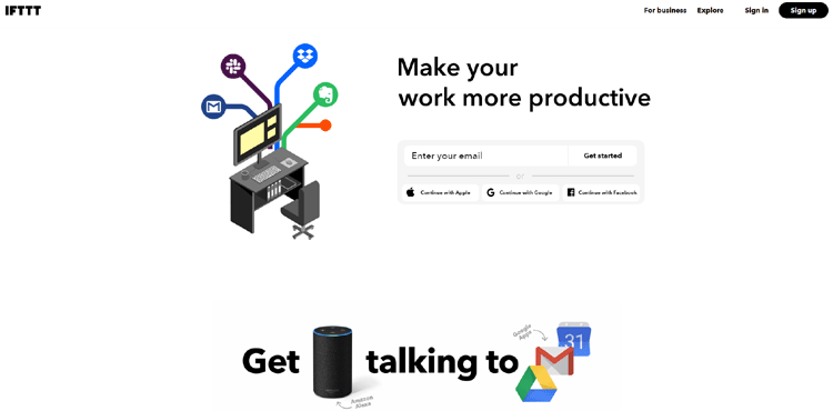
Now, you need to create an Applet. For that, follow the steps below:
To make an applet, click on your account icon and click Create.

In the create screen, Click the + icon after if.

After that, you need to allow access to your google account.
For that, you need to search for Google Assistant in the search bar and click on the Google Assistant icon.
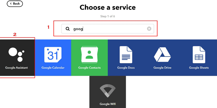
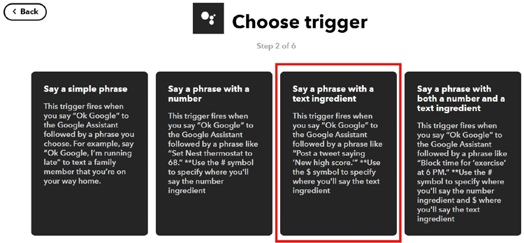
In the Next Screen, we have to choose a trigger,
Remember, we made three blocks in the Adafruit IO Server, we need to make there triggers for those three blocks.
First, the Radio Station Block, for that, we need to select Say a phrase with a text ingredient.
In the next screen, we have to type what do you want to say & what the google assistant should reply to you with.
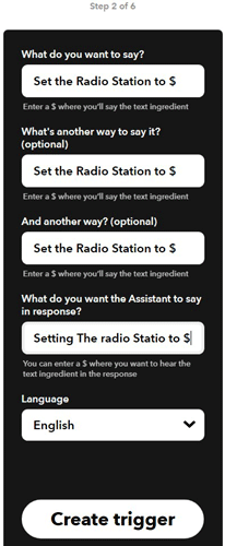
Then click on the Create trigger button.
The next screen looks something like this, as you have completed the If part, it's time for the then part, click the + sign after then.

You will be presented with a screen like the below image, search for Adafruit, and click on the Adafruit icon.
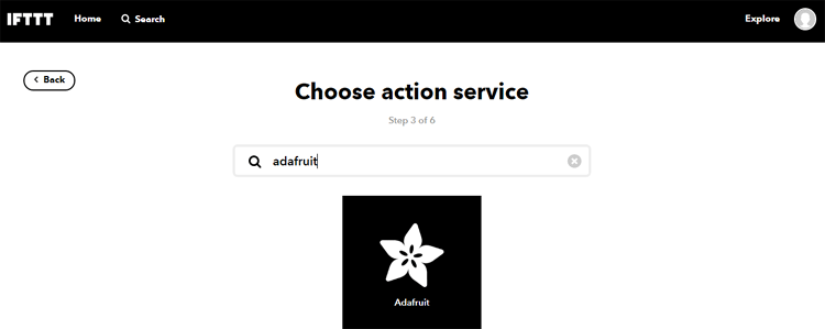
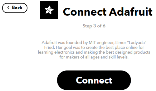
Next, authorize your Adafruit account with IFTTT, then click Connect.
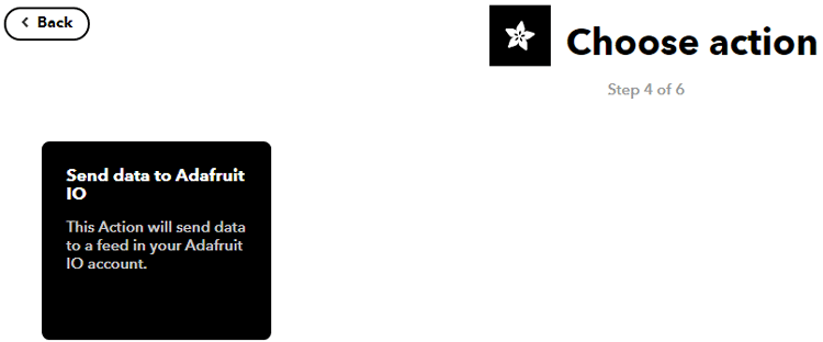
Next, you have to click on Send data to Adafruit IO.
Then you will be presented with a dropdown of feeds that you have created earlier in the Adafruit account.
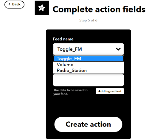
Choose any one and click on create action, you need to do this for all three.
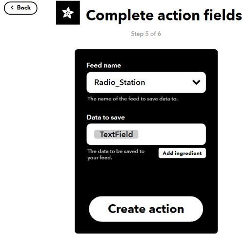
And with that, marks the end of the IFTTT process, my final applet screen looks like this,
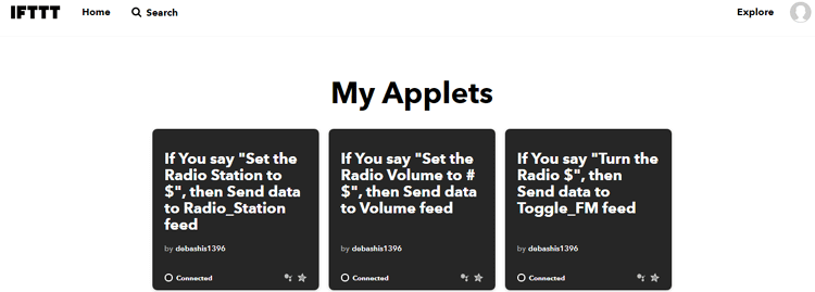
Arduino Code and Explanation
The Arduino code is there to manage all the communication between the IC and the communication between Adafruit IO IFTTT and WIFI. Complete code for this Arduino Nano FM Radio is given at the end of this tutorial. The code is little bit lengthy and complex, here we have explained the complete code line by line.
First, we need to include all the required libraries, they are:
#include <ESP8266WiFi.h> //Library for the ESP8266 NodeMCU Board
#include <Wire.h> //Wire library is needed for I2C communication
#include <PT2258.h> //PT2258 Library is needed to communicate with the IC
#include <RDA5807M.h> // RDA5807M library is used to communicate with the RDA module
#include <Adafruit_MQTT.h> // Adafruit MQTT is need for MQTT
#include <Adafruit_MQTT_Client.h> // Adafruit MQTT is for the MQTT Client
Then, define the SSID and password for the WI-FI, this is the SSID and the PASSWORD of your router.
const char* ssid = "Android"; // SSID of your router
const char* password = "12345678"; // Password of Your Router
Then we define two booleans and a variable, the booleans are used to hold the communication status of the IC’s, and the volume variable is used to set the volume level.
bool potStatus; // 1 when communication is established between the MCU and the IC
bool radioStatus; // 1 when communication is established between the MCU and the IC
int volume = 15; // default volume level with the IC starts with
Then, we set up a GPIO pin named Relay_Pin to turn on or off the amplifier.
#define Relay_Pin D7 // This pin is used to turn on and off the radio
Next, we need to define all the necessary defines to communicate with Adafruit IO.
#define AIO_SERVER      "io.adafruit.com"
#define AIO_SERVERPORT  1883                   // use 8883 for SSL
#define AIO_USERNAME    "debashis13"            // Replace it with your username
#define AIO_KEY  "aio_Qyal47xo1fYhc55QB1lEPEirnoFp"
// Replace with your Project Auth Key
The below definitions FIX_BAND is a proprietary definition used by the library.
The next defined statement sets the internal volume of the module.
#define FIX_BAND     RADIO_BAND_FM   //< The band will be tuned by this sketch is FM.
#define FIX_RADIO_VOLUME   6               ///<  Default volume of the module.
Next, make the required objects for the PT2258, the RDA5807M, and the WiFiClient.
PT2258 digitalPot; // PT2258 Object
RDA5807M radio; //RDA5807M Object
WiFiClient client; //WiFiClient Object
Then set up the MQTT client class by passing in the WiFi client and MQTT server and login details.
Adafruit_MQTT_Client mqtt(&client, AIO_SERVER, AIO_SERVERPORT, AIO_USERNAME, AIO_KEY);
//Setup the MQTT client class by passing in the WiFi client and MQTT server and login details.
Then We need to subscribe to a Feed. What does that make you may ask?
If some values, some parameters change in the Adafruit server, the changes will be reflected here.
Adafruit_MQTT_Subscribe Radio_Station = Adafruit_MQTT_Subscribe(&mqtt, AIO_USERNAME"/feeds/Radio_Station"); // Methods used to subscribe to a Feed
Adafruit_MQTT_Subscribe Toggle_FM = Adafruit_MQTT_Subscribe(&mqtt, AIO_USERNAME"/feeds/Toggle_FM"); // Methods used to subscribe to a Feed
Adafruit_MQTT_Subscribe Volume = Adafruit_MQTT_Subscribe(&mqtt, AIO_USERNAME"/feeds/Volume"); // Methods used to subscribe to a Feed
Below is the function prototype for MQTT_connect() function.
void MQTT_connect();//Function Prototype for MQTT Connect
Then we begin our setup process. At first, we start the UART communication with the begin method.
Serial.begin(9600); //UART begin
Serial.println(); // adds a extra line for spacing
Serial.println();// adds a extra line for spacing
Next, we do all the usual thing to connect to WiFI
**************** all the usual things required for a WiFi connection***********************/
  Serial.print("connecting to ");
  Serial.println(ssid);
  WiFi.mode(WIFI_STA);
  WiFi.begin(ssid, password);
  while (WiFi.status() != WL_CONNECTED) {
    delay(500);
    Serial.print(".");
  }
  Serial.println("");
  Serial.println("WiFi connected");
  Serial.println("IP address: ");
  Serial.println(WiFi.localIP());
/**************** all the usual things required for a WiFi connection***********************/
Next, call the Wire.begin() method to instantiate an I2C connection & we call the Wire.setClock() method to fix the I2C frequency to 100KHz as it's the full speed of the PT2258 IC.
 Wire.begin(); // begin the I2C starting sequence
 Wire.setClock(100000); // setting the I2C clock to 100KHz
Next, call the init() method for both the PT2258 and the RDA5807 IC and hold the return status into the previously defined booleans.
 potStatus = digitalPot.init();
 radioStatus = radio.init();
Next, check if the MCU was able to communicate with the IC or not. We do this with two if else statements.
if (potStatus)  {
    Serial.println("Found PT2258 Device!");
  }
else{
    Serial.println("Failed to Initiate PT2258");
  }
  if (radioStatus)  {
    Serial.println("Found RDA5807M Device!");
  }
  else{
    Serial.println("Failed to Initiate RDA5807M");
  }
Next, call the subscribe method from the MQTT library. We will be notified by the MQTT server if any changes happened in our subscribed feeds.
mqtt.subscribe(&Radio_Station); //Setup MQTT subscription for Radio_Station feed
mqtt.subscribe(&Toggle_FM); //Setup MQTT subscription for Toggle_FM feed
mqtt.subscribe(&Volume);  //Setup MQTT subscription for Volume feed
Next, we set the Relay pin as output and the pin status to LOW
pinMode(D7, OUTPUT);
digitalWrite(D7, LOW);
Next, set a predetermined radio volume, this parameter sets the internal volume of the RDA5807 IC, which marks the end of our setup process.
  radio.setVolume(FIX_RADIO_VOLUME); //next we set the normalize radio volume
  radio.setMono(false); // we do not want the chip to give mono output
  radio.setMute(false); // we don't want the chip to go mute at start
We start the loop by calling the MQTT_connect() function which establishes a connection to the MQTT server.
In the MQTT connect function, we try three times to make a connection to the MQTT server.
If it's successful, we get a Success message else we will get an Error message.
void MQTT_connect()
{
  int8_t ret; // 8 bit integer to store the retries
  // Stop if already connected.
  if (mqtt.connected()) {
    return;
  }
  Serial.print("Connecting to MQTT... ");
  uint8_t retries = 3;
  while ((ret = mqtt.connect()) != 0) { // connect will return 0 for connected
    Serial.println(mqtt.connectErrorString(ret));
    Serial.println("Retrying MQTT connection in 5 seconds...");
    mqtt.disconnect();
    delay(5000);  // wait 5 seconds
    retries--;
    if (retries == 0) {
      // basically die and wait for WDT to reset me
      while (1);
    }
  }
  Serial.println("MQTT Connected!");
}
Next, start by creating a pointer to an Adafruit_MQTT_Subscribe object. We'll use this to determine which subscription was received.
Adafruit_MQTT_Subscribe *subscription;
Next, we wait for a subscription message.
mqtt.readSubscription(timeInMilliseconds) will listen to a certain time, for any messages coming from the MQTT server.
If it gets a message before timeout, it will reply with a pointer to the subscription or it will just time out and return 0. In that case, it will wait for 2 Sec.
while ((subscription = mqtt.readSubscription(20000)))
If a timeout occurs, the while loop fill fails. If not, we compare what subscription and will get our known subscriptions.
In this code, we do this for all three of our subscribed feeds.
if (subscription == &Toggle_FM)
if (subscription == &Radio_Station)
if (subscription == &Volume)
These were the main three parameters that you need to understand in the loop section.
This section of the code is used to monitor & set the Toggle_FM feed.
if (subscription == &Toggle_FM) // is it a message from the Toggle_FM Feed
    {
      Serial.print(F("Got: "));
      Serial.println((char *)Toggle_FM.lastread); //print the Feed data just for debugging
      if (String((char *)Toggle_FM.lastread) == String("on")) // we compare the received data to a known parameter in this case we are expecting that "on" is coming from the sever
      {                                                       // but before we do that we have to make it a string which makes the comparisin super easy
        digitalWrite(D7, HIGH);// if we get a "on" string from the server we are making the D7 pin HIGH
      }
      if (String((char *)Toggle_FM.lastread) == String("off")) // again we are checking for the string off
      {
        digitalWrite(D7, LOW);//if we get a "off" string from the server we are making the D7 pin LOW
      }
    }
This section of the code is used to monitor & set the Radio_Station feed.
 if (subscription == &Radio_Station)
    {
      Serial.print(F("Got: "));
      Serial.println((char *)Radio_Station.lastread);
      if (String((char *)Radio_Station.lastread) == String("Big FM")) // hear we are checking for the string Big FM
      {
        radio.setBandFrequency(FIX_BAND, 9270); // if the above condition is true we are setting the radoi channel to 92.7MHz
      }
      // The above mentioned proces is continued below
      if (String((char *)Radio_Station.lastread) == String("Red FM"))
      {
        radio.setBandFrequency(FIX_BAND, 9350);
      }
      if (String((char *)Radio_Station.lastread) == String("Radio Mirchi"))
      {
        radio.setBandFrequency(FIX_BAND, 9830);
      }
    }
This section of the code is used to monitor & set the Volume feed.
 if (subscription == &Volume) // // hear we are checking for the string Volume and it is an integer value in a string format
                                    // We have to convert it back to an integer to change the volume with the help of the PT2258 IC
      Serial.print(F("Got: "));
      Serial.println((char *)Volume.lastread);
      volume = atoi((char *)Volume.lastread); // We are using the atoi() methode to convert a character pointer to a integer
     volume= map(volume,0,100,79,0); //map(value, fromLow, fromHigh, toLow, toHigh) // as the pt2258 only understand integer values in dB
                                      // we are maping the 0dB - 79dB value to 0% - 100% .
      digitalPot.setChannelVolume(volume, 0); //after all that we are setting the volume for the channel 0 of the PT2258 IC
      digitalPot.setChannelVolume(volume, 1); //after all that we are setting the volume for the channel 1 of the PT2258 IC
    }
  }
Testing the Voice Controlled FM Radio using Arduino
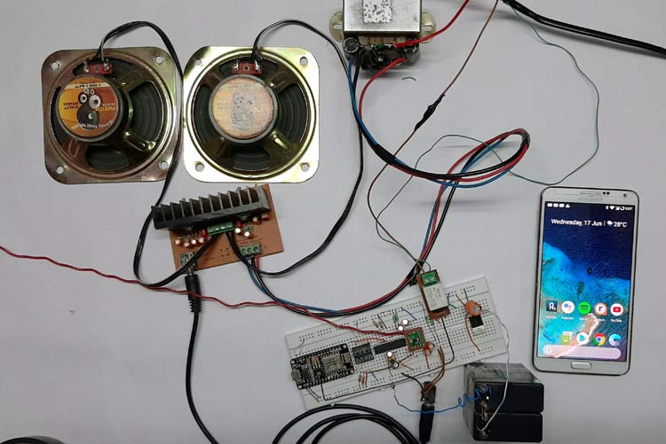
To test the circuit, the following apparatus was used-
- A transformer which has a 13-0-13 Tap
- Two 4Ω 20W speakers as a load.
- Phone to use Google Assistant.
In a previous article, I have shown you how to make a Simple 2x32 Watt Audio Amplifier with TDA2050 IC, I am going to use that for this demonstration, also,
I have disordered the mechanical potentiometer and shorted two leads with two small jumper cables. Now, with the help of two push-buttons, I was able to change the volume of the amplifier.
Further Enhancement
There are many further enhancements that can be made to this circuit.
- There are various noise issues because an audio source is working beside the NodeMCU, so we need to implement additional shielding to improve noise immunity.
- Building the overall circuit to a PCB will improve noise immunity.
- Additional filters can be added to this IC to eliminate noise.
I hope you liked this article and learned something new out of it. If you have any doubt, you can ask in the comments below or can use our forums for detailed discussion.
#include <ESP8266WiFi.h> //Library for the ESP8266 NodeMCU Board
#include <Wire.h> //Wire library is needed for I2C communication
#include <PT2258.h> //PT2258 Library is needed to communicate with the IC
#include <RDA5807M.h> // RDA5807M library is used to communicate with the RDA module
#include <Adafruit_MQTT.h> // Adafruit MQTT is need for MQTT
#include <Adafruit_MQTT_Client.h> // Adafruit MQTT is for the MQTT Client
bool potStatus; // 1 when communication is established between the MCU and the IC
bool radioStatus; // 1 when communication is established between the MCU and the IC
int volume = 15; // default volume level with the IC starts with
#define Relay_Pin D7 // This pin is used to turn on and off the radio
#define AIO_SERVER      "io.adafruit.com"
#define AIO_SERVERPORT  1883                   // use 8883 for SSL
#define AIO_USERNAME    "debashis13"            // Replace it with your username
#define AIO_KEY         "aio_Qyal47xo1fYhc55QB1lEPEirnoFp"   // Replace with your Project Auth Key
//----------------------------------------- TMP_RADIO--------------------------------------
#define FIX_BAND     RADIO_BAND_FM   ///< The band that will be tuned by this sketch is FM.
#define FIX_RADIO_VOLUME   6               ///< The volume that wi
//----------------------------------------- TMP_RADIO--------------------------------------
PT2258 digitalPot; // PT2258 Object
RDA5807M radio; //RDA5807M Object
WiFiClient client; //WiFiClient Object
Adafruit_MQTT_Client mqtt(&client, AIO_SERVER, AIO_SERVERPORT, AIO_USERNAME, AIO_KEY);// Setup the MQTT client class by passing in the WiFi client and MQTT server and login details.
Adafruit_MQTT_Subscribe Radio_Station = Adafruit_MQTT_Subscribe(&mqtt, AIO_USERNAME"/feeds/Radio_Station"); // Methode used to subscribe to a Feed
Adafruit_MQTT_Subscribe Toggle_FM = Adafruit_MQTT_Subscribe(&mqtt, AIO_USERNAME"/feeds/Toggle_FM"); // Methode used to subscribe to a Feed
Adafruit_MQTT_Subscribe Volume = Adafruit_MQTT_Subscribe(&mqtt, AIO_USERNAME"/feeds/Volume"); // Methode used to subscribe to a Feed
void MQTT_connect(); //Function Prototype for MQTT Connect
void setup() {
  Serial.begin(9600); //UART begin
  Serial.println(); // adds a extra line for spacing
  Serial.println();// adds a extra line for spacing
/**************** all the usual things required for a WiFi connection***********************/
  Serial.print("connecting to ");
  Serial.println(ssid);
  WiFi.mode(WIFI_STA);
  WiFi.begin(ssid, password);
  while (WiFi.status() != WL_CONNECTED) {
    delay(500);
    Serial.print(".");
  }
  Serial.println("");
  Serial.println("WiFi connected");
  Serial.println("IP address: ");
  Serial.println(WiFi.localIP());
/**************** all the usual things required for a WiFi connection***********************/
  Wire.begin(); // begin the I2C starting sequence
  Wire.setClock(100000); // setting the I2C clock to 100KHz
  Serial.println("Initiating Radio With Digital Pot...");
  delay(200);
  potStatus = digitalPot.init(); // boolean used for status checks
  radioStatus = radio.init(); // boolean used for status checks
  if (potStatus)
  {
    Serial.println("Found PT2258 Device!");
  }
  else
  {
    Serial.println("Failed to Initiate PT2258");
  }
  if (radioStatus)
  {
    Serial.println("Found RDA5807M Device!");
  }
  else
  {
    Serial.println("Failed to Initiate RDA5807M");
  }
  mqtt.subscribe(&Radio_Station); //Setup MQTT subscription for Radio_Station feed
  mqtt.subscribe(&Toggle_FM); //Setup MQTT subscription for Toggle_FM feed
  mqtt.subscribe(&Volume);  //Setup MQTT subscription for Volume feed
  pinMode(D7, OUTPUT);
  digitalWrite(D7, LOW);
  radio.setVolume(FIX_RADIO_VOLUME); //next we set the normalize radio volume
  radio.setMono(false); // we do not want the chip to give mono output
  radio.setMute(false); // we donot want the chip to go mute at start
}
void loop() {
  MQTT_connect();  //call this functio to connect to the MQTT Server
  Adafruit_MQTT_Subscribe *subscription; // we make a pointer to Adafruit_MQTT_Subscribe object.
  while ((subscription = mqtt.readSubscription(20000))) // We check to see if there is any new message from the server or not
  {
    if (subscription == &Toggle_FM) // is it a message from the Toggle_FM Feed
    {
      Serial.print(F("Got: "));
      Serial.println((char *)Toggle_FM.lastread); //print the Feed data just for debugging
      if (String((char *)Toggle_FM.lastread) == String("on")) // we comparair the received data to a known parameter in this case we are expecting that "on" is comming from the sever
      {                                                       // but before we do that we have to make it a string which makes the comparisin super easy
        digitalWrite(D7, HIGH);// if we get a "on" string from the server we are making the D7 pin HIGH
      }
      if (String((char *)Toggle_FM.lastread) == String("off")) // again we are checking for the string off
      {
        digitalWrite(D7, LOW);//if we get a "off" string from the server we are making the D7 pin LOW
      }
    }
    if (subscription == &Radio_Station)
    {
      Serial.print(F("Got: "));
      Serial.println((char *)Radio_Station.lastread);
      if (String((char *)Radio_Station.lastread) == String("Big FM")) // hear we are checking for the string Big FM
      {
        radio.setBandFrequency(FIX_BAND, 9270); // if the above condition is true we are setting the radoi channel to 92.7MHz
      }
      // The above mentioned proces is continued below
      if (String((char *)Radio_Station.lastread) == String("Red FM"))
      {
        radio.setBandFrequency(FIX_BAND, 9350);
      }
      if (String((char *)Radio_Station.lastread) == String("Radio Mirchi"))
      {
        radio.setBandFrequency(FIX_BAND, 9830);
      }
    }
    if (subscription == &Volume) // // hear we are checking for the string Volume and it is an integer value in a string format
                                    // We have to convert it back to a integer to change the volume with the help of the PT2258 IC
      Serial.print(F("Got: "));
      Serial.println((char *)Volume.lastread);
      volume = atoi((char *)Volume.lastread); // We are using the atoi() methode to convert a character pointer to a integer
     volume= map(volume,0,100,79,0); //map(value, fromLow, fromHigh, toLow, toHigh) // as the pt2258 only understand integer values in dB
                                      // we are maping the 0dB - 79dB value to 0% - 100% .
      digitalPot.setChannelVolume(volume, 0); //after all that we are setting the volume for the channel 0 of the PT2258 IC
      digitalPot.setChannelVolume(volume, 1); //after all that we are setting the volume for the channel 1 of the PT2258 IC
    }
  }
}
void MQTT_connect()
{
  int8_t ret; // 8 bit integer to store the retries
  // Stop if already connected.
  if (mqtt.connected()) {
    return;
  }
  Serial.print("Connecting to MQTT... ");
  uint8_t retries = 3;
  while ((ret = mqtt.connect()) != 0) { // connect will return 0 for connected
    Serial.println(mqtt.connectErrorString(ret));
    Serial.println("Retrying MQTT connection in 5 seconds...");
    mqtt.disconnect();
    delay(5000);  // wait 5 seconds
    retries--;
    if (retries == 0) {
      // basically die and wait for WDT to reset me
      while (1);
    }
  }
  Serial.println("MQTT Connected!");
}
