When designing a microcontroller-based product, it is crucial to include a programming connector on the PCB. Without it, flashing the firmware to the MCU becomes impossible. However, this connector can take up precious board space, which is a significant issue for size-constrained designs. To address this, designers often use techniques like test points with specialized jigs or preprogramming MCUs before soldering using ZIF sockets. While effective, these methods require special equipment and involve time-consuming manufacturing steps.
Youtuber Tim Alex Jacobs encountered these issues while working on his LED badge project. Inspired by the principles of optical communication, Tim devised an innovative solution. His LED badge, which is densely packed with LEDs, repurposes these LEDs as light sensors to program the microcontroller using light. As we know LEDs can generate a small voltage when exposed to light due to the photovoltaic effect, acting like micro solar cells. Light has long been used for communication, from infrared link cables to high-bandwidth optical fiber networks. Tim combined these ideas to create a straightforward way to program the MCU on his badge. He developed a web app that uses any LCD display to program the MCU.
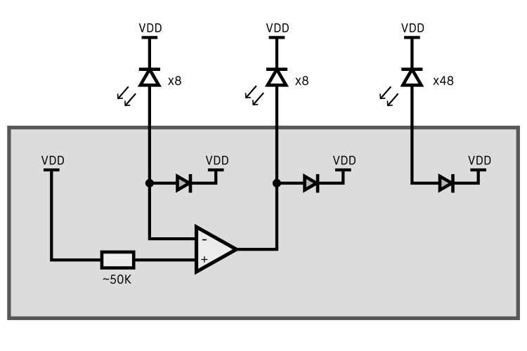
The basic principle is simple: zeros and ones are represented by dark and light spots on the display. Depending on the data bits, the web app controls the designated display area. When the LEDs are placed over this area, they generate different voltages based on the display pattern, which is then decoded into a data stream. Tim utilized the on-chip OpAmp comparators in the CH32V003, achieving a data rate of up to 1,000,000 baud with zero percentage error. He explains it further in his YouTube demonstration video.