Nowadays there are a lot of IoT development boards available. But if you look at the AI IoT development board the options are very limited. Even within them, the ones with good performance tend to be expensive, and the ones that are cheap don’t provide enough performance or are limited in some other way. Just like you, we have also been looking for an AI IoT board, that is not that expensive and comes with good performance. That was when we came across the Sipeed MaixDuino Ai Development kit. It is not only reasonably priced but also comes with a lot of useful features and peripherals. That's why we chose this as one of three boards for our upcoming IoT & Edge AI Project Challenge where you can win prizes up to Rs.7,00,000. Not only that you can even win development board and other exciting gooding by just submitting your project ideas. So don’t forget to check out the IoT & Edge AI Project Challenge for more details.
Powered by the Sipeed M1 AI module the Maixduino also comes with exciting features such as an ESP32 co-processor for WiFi and Bluetooth connectivity, a 2.4” LCD, a VGA image sensor, a microSD card slot and an onboard MEMS microphone. All these are packed into an Arduino Uno sized board which is pin compatible with the Arduino Uno R3.
Let’s Unbox It
Now let’s check out the Maixduino package contents. The development board and all its extra components come in a sturdy plastic box which provides protection from any damages.
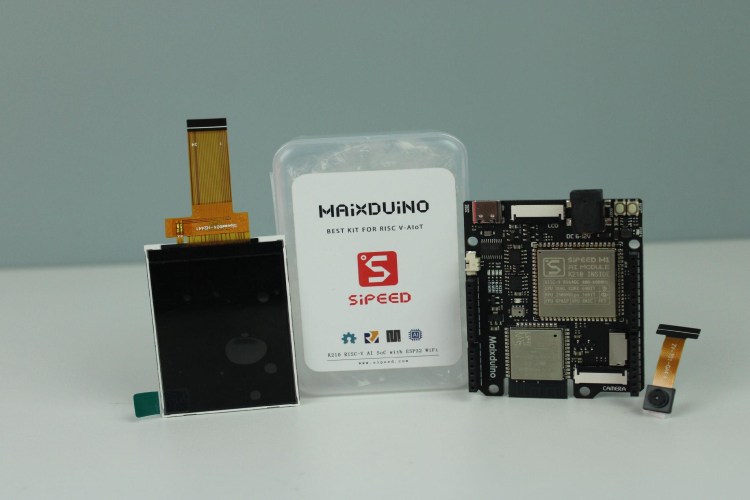
Within the box, you will find the Maixduino AI development board itself with the 2.5” LCD display and GC0328 VGA Camera Module.
Sipeed MaixDuino Ai Development Kit Features
As we said earlier the Sipeed MaixDuino Ai Development kit is packed with a lot of features. Here are some of the main features listed.
- Core RISC-V Dual Core 64bit, with FPU
- Frequency 400MHz (Can be overclocked to 600MHz)
- SRAM built-in 8MB
- Image Recognition QVGA@60fps/VGA@30fps
- Speech Recognition Microphone array (8mics)
- Deep Learning Framework: Supports TensorFlow, Keras, Darknet, Caffe, and other mainstream frameworks
- Peripherals FPIOA, UART, GPIO, SPI, I2C, I2S, TIMER
- Video Processing
- Neural Network Processor (KPU)
- FPU Meets IEEE754-2008 Standard
- Audio Processor (APU)
- Fast Fourier Transform Accelerator (FFT)
- Built-in neural network processor
- Connector: compatible with Arduino interface, TF card slot, speaker port
- Wireless: Support 2.4G 802.11.b/g/n and Bluetooth 4.2
- Audio: MEMS microphone, 3W speaker output
- DVP Camera Interface: 24P 0.5mm FPC connector, support OV2640, OV5640, OV7740, etc.
- LCD Interface: 24P 0.5mm FPC connector; support 8bit MCU LCD
- ESP32 Module: For WiFi and Bluetooth Connectivity
- Development Environment: support for Arduino IED, MaixPy IDE, OpenMV IDE
- 2.4” 320x240 SPI TFT Display
- GC0328 camera VGA Camera module
Sipeed Maixduino AI Development Board Hardware Overview
As you have familiarised yourself with the features, let’s look at the hardware overview for the Sipeed Maixduino Development Board. The Sipeed Maixduino Development Board has all of its components assembled on the same side. Here are parts marking images introducing each main component.
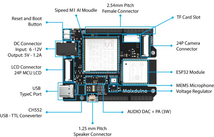
The main attraction on the Sipeed Maixuino development board is of course the Sipeed M1 AI module. The Sipeed M1 module is based on the K210 RISC-V AI processor from Kendryte. K210 comes with a dual-core processor chip with independent FPU, 64-bit CPU width, 8 MB on-chip SRAM, 400 adjustable clock frequency, and double-precision FPU supporting multiplication, division, and square root operation. It also has AI features such as neural network hardware accelerator KPU, voice processing unit (APU), programmable IO array (FPIOA/IOMUX), and Fast Fourier Transform Accelerator. In AI processing, K210 can perform operations such as convolution, batch normalization, activation, and pooling. At the same time, the pre-processing of voice direction scanning and voice data output can also be performed.
For WiFi and Bluetooth connectivity, the Sipeed Maixduino uses an ESP32-WROOM module. Not only that some of the pins are broken out to the Arduino style header for custom usage.The board can be powered from either the DC connector or the USB type C port. The DC barrel connector can accept an input voltage of 6 -12V DC. There are two tactile switches available onboard, one is for board reset and one is for board boot selection. For programming and debugging the Sipeed Maixduino uses a CH552 USB microcontroller. With the specialised ch55x_dualserial firmware the CH552 can create two virtual UART ports which can be used to program the Sipeed M1 module as well as the ESP32 module. It also can automatically detect ESP32 & K210 bootloader messages, and force it to enter ISP mode without the need for any hardware flow control.
The Sipeed Maixduino also contains an MSM261S4030H0 MEMS microphone for audion capturing, a TM8211 DAC for I2S audio decoding and a 3W PA built around NS4150 for audio out. The PA output can be directly connected to a 3W speaker through the 1.25mm pitch JST connector. The board also has an RGB LED located near the MEMS microphone for use outputs. Other LEDs onboard include the power LED along with RX and TX indication LEDs for both Sipped M1 module and ESP32. It also has an onboard microSD card slot for storage explanation. For interfacing the TFT display the board uses a 24-pin 0.5mm FPC connector. The display comes with the kit is a 2.4” ST7789 TFT display with a resolution of 320x240 pixels, and it uses an 8-bit bus for interfacing with the M1 module. The 24-pin camera FPC interface supports various camera modules including OV2640, OV5640, OV7740 and GC0328.
Sipeed Maixduino AI Development Board Pinout
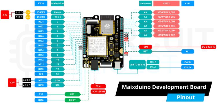
The above pinout image clearly shows the basic as well as alternate function of each pin on the Maixduino development board. As you can see some of the pins are directly connected to the Sipeed M1 module while some of them are connected to the ESP32 module. All of the digital pins are attached to the M1 module, while all of the analog pins are attached to the ESP32 SoC.
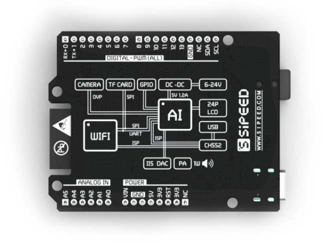
Even though the shape and pins are compatible with Arduino UNO R3, the output voltage levels of the GPIOs are different. The Maixduino only supports 3.3V and 1.8V in its GPIOs, which requires great attention when interfacing with external components, otherwise, the board can be damaged. The reset pin is only 1.8V compatible, be careful when using it. The board also comes with the basic Arduino style pin labelling on the bottom of the PCB.
Using the Sipeed Maixduino with Arduino IDE
In terms of software support also the Maixduino doesn’t disappoint us. The Sippeed Maixduino supports many popular frameworks such as MaixPy IDE, PlatformlO IDE and last but not least our favourite the Arduino IDE. It also supports various real-time operating systems such as Free-RTOS and RT-Thread. So our article will be using the Arduino IDE since it is very popular and easy to use. You can find detailed instructions on how to set up the Maixduino IDE can be found in the official Miaxuino documentation. To start with open up the Arduino IDE and add the following URL to the additional board manager URL section in the Arduino IDE preferences.
http://dl.sipeed.com/MAIX/Maixduino/package_Maixduino_k210_index.json
After closing the Arduino preference window search and install the Miaxuino board package through the board manager.
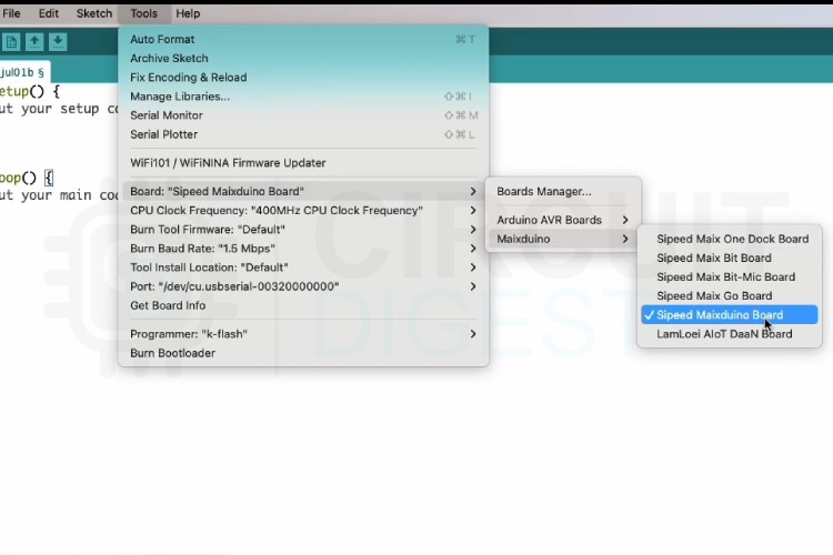
Once installed select the Miaduino board from the tools menu and also select the appropriate serial port. When connected the device will show two serial ports, select the first one. In the progamer option select the k-flash programmer. If you don’t select it you won’t be able to program the board. Leave other options as same as the default.
Caution: Now before moving forward. some of the libraries that come with the Maixduino board package are old and can cause some compiler errors. To overcome that please go to the Maixduino GitHub repository and download the library folder. Copy all the libraries, except the Adafruit_GFX library within the library folder to the library folder in the board package installation path. When asked to replace all the files.
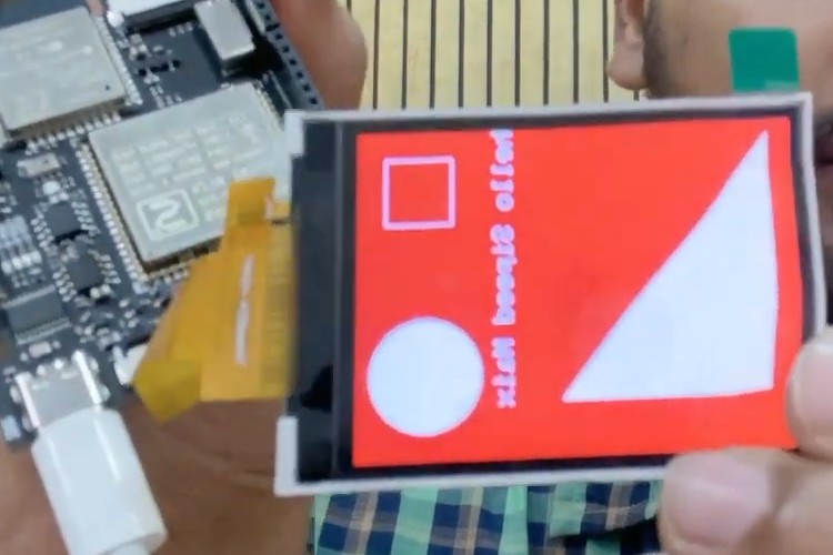
To start with let’s open up an example file. Open the basic display example code under the Sipeed_ST7789. Compile the code and upload it to the board. Now the board will display some basic shapes and text on the TFT display. Ensuring everything is working accordingly.
Caution: If you face any errors while uploading such as “a programmer is needed for uploading” make sure you have selected k-flash as the programmer in the tool's menu. If the problem still persists, use the upload using the programmer option from the Sketch menu instead of the upload button. If you face a timeout error while uploading, reset the board while holding down the boot button and try uploading the error. If the board is stuck at FT2232 mode with the warning “recv unknown op 96”, change the baud rate to 1Mbps and try the uploading and when it fails change the baud rate to 1.5Mbps and upload again. If you face any error related to the Arduino_GFX library during compilation make sure to remove any existing versions and install version 1.4.8 of the Arduino_GFX library.
To test the camera, open up the sipeed_gc0328 example you can find on the updated libraries you have downloaded from the GitHub. This example will display the video feed from the camera on the TFT screen.
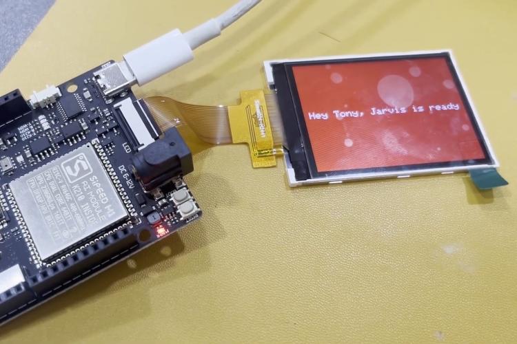
The Maixduino also support many advanced applications such as face recognition, speech recognition and many other AI applications. You can find examples for all of these applications in the GitHub repo we have provided before. Before concluding we can also look at one more example, and for that I have selected a speech recognition example. For this, we are going to use the Maix-SpeechRecognizer library by Andri. Download the voice_model.h file and the main.c file to a folder. Rename the main.c file into an ino file and open it with the Arduino IDE. Make sure the sketch file and the voice_model.h file is in the same folder.
Once the code is uploaded the code, you can interact with the board using the catchphrases “Hey, Friday” or “Hey, Jarvis”. The board will pick your voice through the onboard MEMS microphone, and it will run a speech recognition algorithm on it. To know more about how to train your own catchphrase and how to use it please watch the video attached below. You will also find more details on the board usage and examples we have discussed earlier in the video.