When it comes to the development board there are a ton of choices to choose from, such as Arduino boards, ESP32 development boards, STM32 Nucleo and Discovery boards, Teensy Boards, STM8 development boards and many more. However, the problem with most of these boards is that it is hard to find a price-to-performance balance. They are either cheap and lack features and performance or they are packed with features and performance with a hefty price tag. Even if you can find a board with a cheap price tag and better performance it most likely will lack any device support. With that in mind, I would like to draw your attention to the MAX78000FTHR development board from Analog Devices.
The MAX78000 Feather development board comes with a ton of features, including an ARM Coretex M4 processor with Risc-V coprocessor, Convolutional Neural Network Accelerator, CMOS VGA Image Sensor, Stereo Audio CODEC, Digital Microphone, On-Board DAPLink debugger and many more with price of only 32USD. It is designed for ultra-low-power, artificial intelligence (AI) applications. The MAX78000 feather board is not only packed with features, but it also gets great support from the manufacturer, Analog Devices. You can get almost all possible example codes with detailed explanations for easy learning and development.
So in this article, we will be reviewing the MAX78000 Feather development board, and we will go through its features, uses, and example codes. We have also selected the MAX78000 Feather development board for our IoT & Edge AI Project Challenge as one of three boards you can choose from. Check out the contest page for more information and don’t miss the chance to get a MAX78000 Feather development board and other interesting goodies along with a chance to win prizes up to Rs.7,00,000.
It’s Unboxing Time!
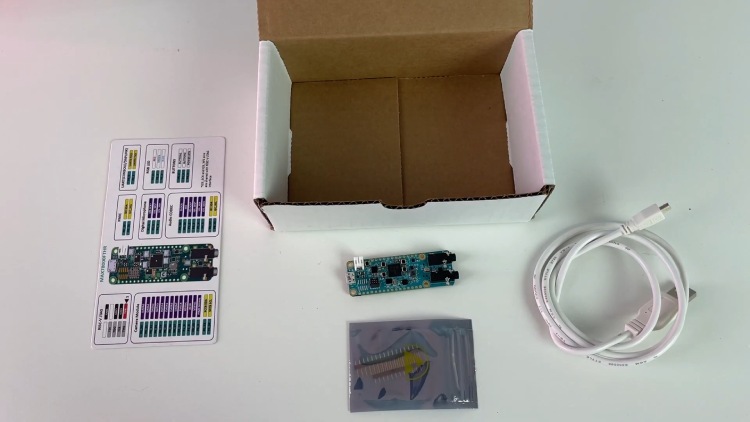
Now let’s unbox the MAX78000 feather board. The MAX78000 feather board comes in a sturdy cardboard box. The box contains the board itself, along with a USB cable, a pinout image, and header pins to be soldered to the board. The board is secured in a reusable ESD bag to protect it from any static electricity during shipment or handling.
MAX78000 Feather Development Board Features
As we said earlier the the MAX78000 development board is packed with a lot of features. Here are some of the main features listed.
MAX78000 Microcontroller
- Dual Core: Arm Cortex-M4 Processor with FPU, 100MHz, RISC-V Coprocessor, 60MHz
- 512KB Flash Memory
- 128KB SRAM
- 16KB Cache
- Convolutional Neural Network Accelerator
- 12-bit Parallel Camera Interface
- MAX20303 Wearable PMIC with Fuel Gauge
- Charge from USB
- On-board DAPLink Debug and Programming Interface for Arm Cortex-M4 processor with FPU
- Breadboard Compatible Headers
- Micro USB Connector
- Micro SD Card Connector
Integrated Peripherals
- RGB Indicator LED
- User Pushbutton
- CMOS VGA Image Sensor
- Low-Power Stereo Audio CODEC
- Digital Microphone
- SWD Debugger
- Virtual UART Console
- 10-Pin Cortex Debug Header for RISC-V Coprocessor
MAX78000 Feather Development Board Hardware Overview
Now let’s look at the hardware overview for the MAX78000. Here are the parts marking for the MAX78000 feather board top side.
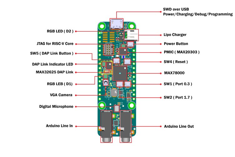
As you can see the board comes with a lot of peripherals. The Micro USB port is used for powering the board as well as for charging, debugging and programming the feather board. The data pins of the USB are directly connected to the MAX32625, which is used for the DAP-Link interface. There an extra JTAG connector is available for debugging the RISC-V core. The board features a JST battery connector for LiPo batteries. This makes it easier to build portable devices and projects with this board. The power management for the entire board is managed by the MAX20303 power management controller. It also contains a fuel gauge feature, which will be useful to detect the state of charge of the connected battery. If we come to the peripherals, the MAX78000 feather board features 2 RGB LEDs, 5 tactile buttons, and a digital microphone. A VGA camera, and Audion line in and out connectors. Out of four tactile switches, one is used as a power button, one is used for the DAP link, one is for reset and the other two are for general usage. The SPH0645LM4H-B digital microphone is directly connected to the MAX78000 processor through the I2C interface. The OVM7692 VGA image sensor is also directly connected to the MAX78000 through the I2C and PCIF interface. The audio input and output are handled by the onboard MAX9867 stereo codec chip. This makes it easier to develop audion-related projects with very minimal software audio processing.
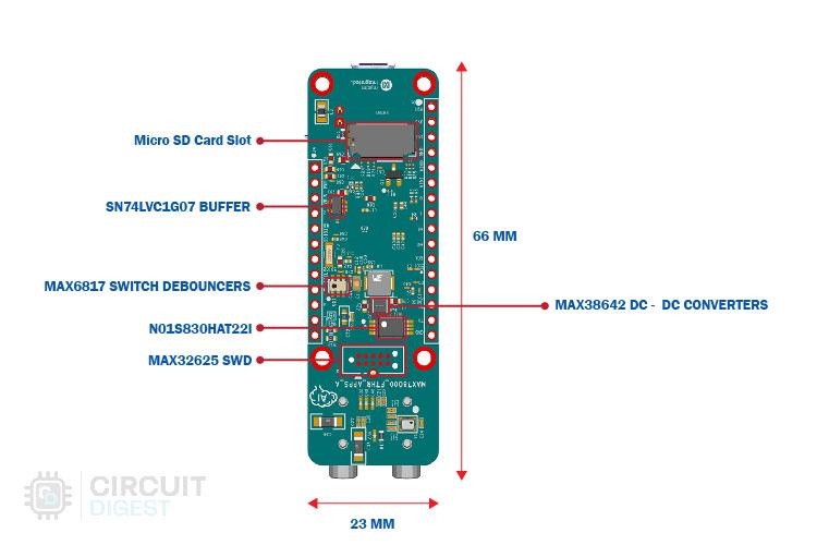
On the bottom side, we have the SD card slot which is interfaced with the MAX78000 through SPI. Other than that, we have the SWD connections for the MAX32625 along with the 1MB QSPI SRAM and some other complimentary circuitry.
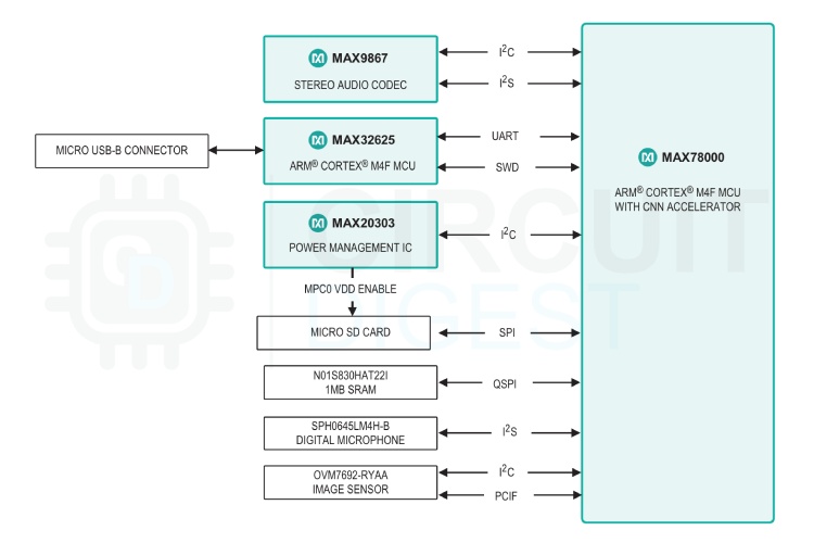
The above image represents the application platform diagram of the MAX78000 feather board. In this, you can see all the peripherals and their corresponding interfacing buses.
MAX78000 Feather Development Board Pinout
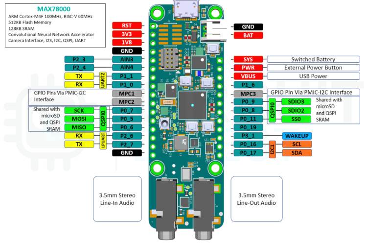
This board comes with 17 GPIOs that are directly connected to the MAX78000, with two of them being analog input pins. It also has 3 more additional GPIO via the I2C interface of the PMIC. Among the available GPIOs, the MAX78000 board has two UART ports, one I2C port and one QSPI port. The QSPI interface is shared with the MicroSD and the QSPI SRAM. So keep that in mind while designing the projects.
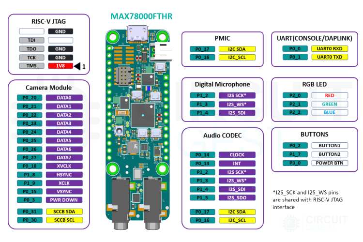
The above image shows the connection between the MAX78000 processor and the onboard peripherals. This is very useful for understanding the structure and working the the standard peripheral libraries provided by Analog Devices.
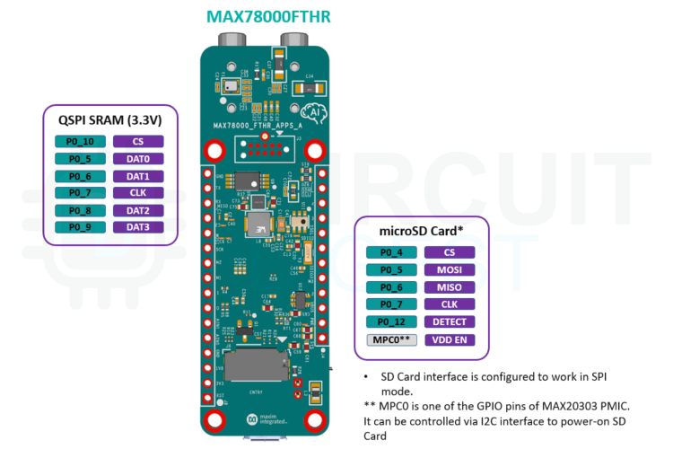
Similarly, the above image shows the SRAM and Micro SD card connections to the MAX78000. Note that the VDD enable pin for the micro-SD card is connected to one of the GPIOs of the PMIC. You can control it via the I2C interface to enable or disable the micro-SD card.
It is Time to Test the Board
Just like most of the development boards, the MAX78000 feather board also comes with a demo program pre-programmed. Unlike most simple boards that come with basic blinky examples, the feather boards come with a fairly complex, but easy-to-use demo program. The Demo program is actually a keyword-spotting demo, which can detect certain voice commands or keywords using the onboard microphone. The demo code can recognize numbers from one to ten and the other two commands go and stop. Based on the number we prompt the board will then blink the onboard RGB LED that many times. For example, if we say four it will blink four times, if we say two it will blink twice.
So, to start with the demo code connect the board to a PC using the micro-USB cable, and it will show as a drive as well as a serial port. So, to understand the demo program a little better, we can use any serial monitor by checking the debug messages. To do so open any serial terminal program such as putty or you can use the serial monitor available in the Arduino IDE. Once connected select the appropriate COM port in the serial terminal and set the baud date to 115200. Now you will be able to see the debug message printed over the UART.
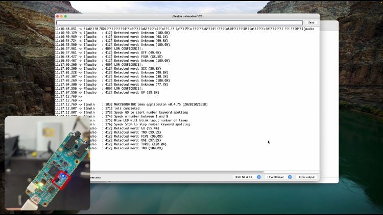
As you can see whenever a sound is detected the demo program will analyze it and if a keyword is detected it, will print out the result on the serial monitor and will blink the LED that many times. If the detected word is unknown, it will show that too.
Coding Our Own - Installing and Using Maxim Micros SDK
Just like Arduino IDE, Analog Devices provides its own development platform for the MAX78000 feather and similar boards, called the Maxim Micros SDK. To start with, go to the MAXT78000FTHR product page, and at the bottom of the page use can find the download links for the Maxim Micro SDK under the tools and simulations section. Download the package that is appropriate to the operating system you are using. Once downloaded install the SDK by following the onscreen instructions. Once installed you can find a folder named MaximSDK in the C drive, if you are using Windows. You can also find that the Eclipse IDE is also installed as a part of this SDK.
To start programming launch the Eclipse IDE. If you want to create a new project, you go to the file menu, select new and then select Analog Devices Microcontrollers. But we would recommend you try some of the sample programs that Analog Devices provide. To open a simple code, select import from the file menu, then select existing project into workspace, and click on next.
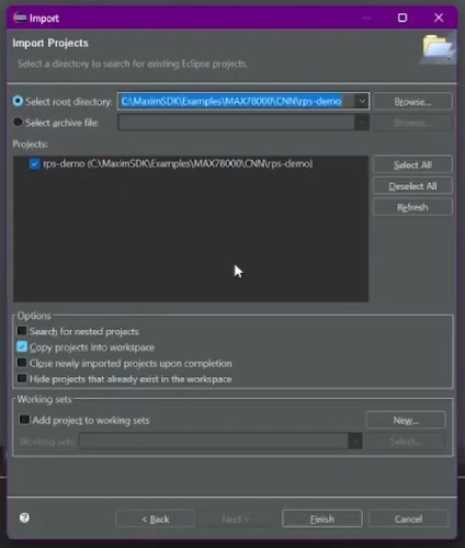
In the import window click on browse and select the root folder of any example code. You can find all the example codes within the MaximSDK folder located in the C drive. For this tutorial, we have selected the keyword sighting project, the one that came with the board, which can be found in the MaximSDK/Examples/MAX78000/CNN/kws20_demo. Select that particular folder and import the project. Once the project is imported you can see a lot of files and folders under the project file tree. In those let's look at the most important ones. The readme file will contain all the information about the project we need. You can go through it to understand the project and it's functioning a bit better.
Next the main.c file will contain the code for the project as usual. Next before compiling the project, we need to do some board-specific build setting. This is because the Maxim Micros SDK support different boards, and the example codes are written in a way that can be used with any of the supporting boards. So, to start, open the project.mk file and recommend the feather board definitions, that is BOARD=FTHR_RevA. Save that file and then open the make file. In the make file we need to set the build target, to do so change the line BOARD ?= EvKit_V1 to BOARD ?= FTHR_RevA. Save the file and now we can compile the project by clicking on the build button. Once the code is compiled successfully, we can click on the launch button to upload the code to the board. While the code is being uploaded the DAPLink Indicator LED will flash rapidly.
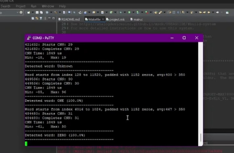
Once done open any serial monitor program and select the appropriate port and baud rate. As you can see in the above image, the sample program is similar to the one that came with the board and detects certain keywords and reacts accordingly.
Similarly, you can go through the other examples and get a grab on how they work and how to modify them to fit our need. Check out the video below for more information on how to use the MAX78000 Feather Development Board.
Overall, the MAX78000 feather development board is a very good option for both beginners and advanced users. Not only it is a powerful and easy-to-use development tool, but also the manufacturer Analog Devices provides a a ton of example codes and documentation. The development environment is easy to set up and doesn't need any lengthy procedure like some other development environments.