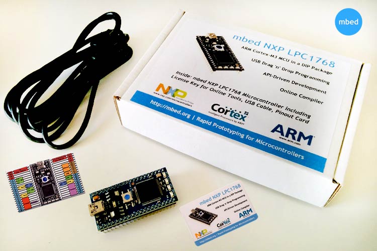
Are you a DIY or an IoT or enthusiast who is planning to start their voyage into the mysterious lands of embedded systems or someone who is planning to up their game from an “8-bit microprocessor” to something more powerful? Or maybe, you are a seasoned engineer, in the proof of concept phase, deciding on a module for prototyping your next consumer grade product and trying to narrow down on a development board for quick and easy initial phase testing of your world changing product. An MBED NXP LPC1768 development board might be a perfect fit for you. But in the world of electronics, a one fit solution seldom happens!!
In this article, I will be reviewing the LPC1768 development board powered by ARM cortex M3 architecture. I will be explaining to you about its feature, uses, and how to upload a code with a simple example using the MBED’s web based IDE so that you can decide if this is the right module for you or not. If you are interested in the LPC series, then you can also check out the LPC2148 Development board for more tutorials and projects.
Time for Unboxing!
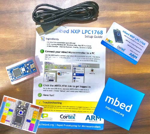
In the box, the first thing, we come across is a quick start guide, which gives us a brief info of getting started with Mbed. Next thing which we can see in the box is the LPC1768 development board, and a couple of cards, one made from plastic and the other from paper with description about the I/o pins and different peripherals. Apart from this we also have a USB cable which will come handy while connecting your MBED with the PC. And the last article is an MBED sticker.
The MBED NXP LPC 1768 Development Board
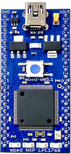
It belongs to the family of ARM cortex M3 Architecture. Here, ARM stands for the Advance RISC Machine, where the word RISC denotes Reduced Instruction Set computer, from the name itself we can tell that it is just like a small or mini-computer which requires fewer instruction as compared to most other conventional microcontrollers. I will be explaining about it later in the article.
Albeit resembling the Arduino nano, this development board packs a lot of punch for most of the hobbyists.
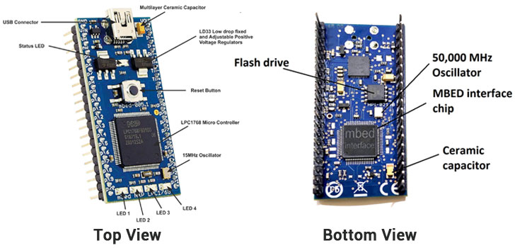
Taking a look at the component of this development board, we can see the LPC 1768 processor, then we have 4 user programmable LEDS at the bottom, later in the video, I will be demonstrating it with a simple code, next we have a reset button, which is used for resetting the target, and a USB connector, we also have a couple of LD33 low and fixed drop voltage regulators and 40GPIOs.
In the reverse side, we have another microprocessor, named magic chip called the MBED interface chip, then this one is a flash drive from Adesto.
This board has got a lot of peripherals, looking at the card, we can see that it has an onboard Ethernet, USB host, and USB Device, i.e. the USB controller is available as the client, host and OTG. It also has 3 Serial Bus, 2 I2C, 1 CAN bus, 6 pins for analog input, 1 pin for analog output, and 6 pins for PWM. The analog output in our development board is connected to the DAC.
Coming to the brain of the board
It basically has 2 processors, 1st ARM Cortex M3, and an extra processor at the back of the board called the MBED interface, which is essential for providing the USB connection to the host computer. A physical UART connection exists between the target and the interface which is relayed over interface USB Serial port. It also helps in programming the ARM processor through JTEG, it also helps in USB to UART conversion so when you connect a USB cable to computer you both see the MBED board as a USB to serial device as well as a USB flash drive. This is where the MBED becomes handy as when you like to program the MBED you just transfer the image file to the flash memory. The flash memory is read by MBED interface and it takes care by programming the binary image file to the LPC1768 microprocessor.
So, basically, the MBED interface controller chip is like an extrovert friend helping his powerful but introvert friend (LPC 1768) communicate better.
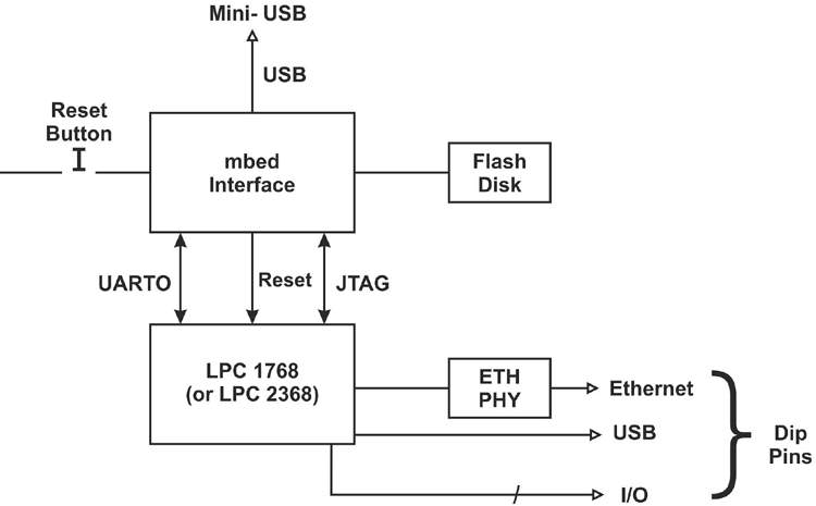
The above figure shows how the MBED interface chip connects the LPC1768 with different peripherals.
Also, you can see in the image above, the reset button on the microcontroller is connected through the interface chip, which means that it does not resets the target directly but ask the interface chip to see if there is any newer binary on the USB flash disk, which has to be programmed.
Coming to the ARM Cortex M3 Microprocessor
It comes from the family of M-series of processor, where M stands for microcontroller. ARM also has A-series which stands for Application profile which is used for advance application and open application platform and the 3rd series called the R-series, which stands for real time profile which is used for real time.
The M3 processor is developed specifically for microcontrollers, to be used in embedded systems, automation, IoT application and motor control application as it has a dedicated motor control PWM output supporting 3 phase motor control.
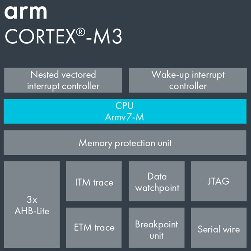
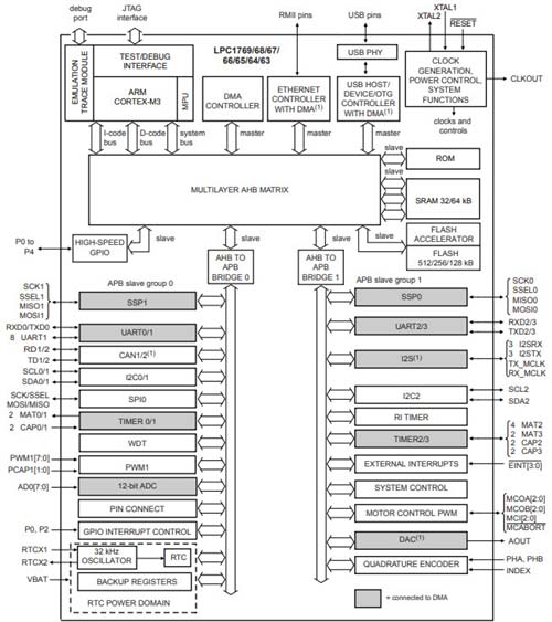
As you can see in the image, there are 3 AHB-Lite busses, namely the system bus, the D-code bus and the I-code Bus. The I-Code and D-code are used for fetching the instruction and data access respectively and are also faster than the system bus.
It has a 3 staged instruction pipeline and Harvard based architecture which helps in utilizing the internal blocks or functional blocks more efficiently.
Basically, there are a lot of features such as:
- 100 MHz operation
- 512 kB flash memory
- 64 kB SRAM
- Nested vectored interrupt controller for fast deterministic interrupts
- Wakeup interrupt controller allows automatic wake from any priority interrupt
- Memory protection unit
- Four reduced-power modes: sleep, deep sleep, power-down and deep power-down
Coming to the peripherals
Since the development board is based on this microprocessor, thus it has all the peripherals the development board offers, I have listed all peripheral below:
Serial Peripherals
- 10 / 100 Ethernet MAC
- USB 2.0 full-speed device / host / OTG controller with on-chip PHY
- Four UARTs with fractional baud rate generation, RS-48, modem control, and IrDA
- Two CAN 2.0B controllers
- Three SSP / SPI controllers
- Three I2C-bus interfaces with one supporting fast mode plus (1-Mbit/s data rates)
- I2S interface for digital audio
Analog peripherals
- 12-bit ADC with eight channels
- 10-bit DAC
Other peripherals
- Ultra-low-power (< 1uA) RTC
- General-purpose DMA controller with eight channels
- Up to 70 GPIO
- Motor control PWM and quadrature encoder Interface to support three-phase motors
- Four 32-bit general-purpose timers/counters
This microprocessor has an ADC block which makes the processor redundant during the Analog to Digital conversion, the ADC requires the data to be accessed from the memory so the controller gives the authority to the DMA controller and transfer the control to DMA control during these operations.
Potential applications of this development board:
This development board is specifically designed to be used in automation, IoT application and motor control application as it has a dedicated motor control PWM output supporting 3-phase motor control. You can also connect it with services such as thingspeak to to perform home automation task and ask specific sensor data or to perform tasks such as tweeting or sending an e-mail. So, this development board is perfect for IOT application, automation and the only limiting factor is your imagination.
How you can upload code in this microcontroller
You can either use Keil microvision, MBED studios and Eclipse or a web based MBED IDE. The language of the mbed platform is C and C++. I will show you how you can upload programs in your microcontroller with an MBED’s online IDE.
MBED Platform
It is an online development platform capable of programming all M-series microcontroller. LPC1768 was the first microcontroller released for the MBED platform.
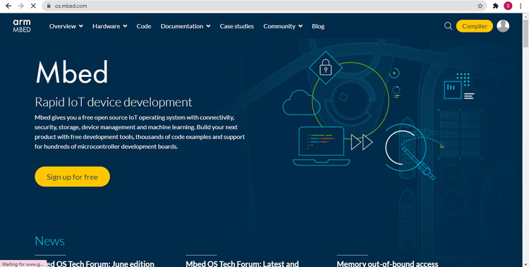
The best part about mbed platform is that you only require a web browser and a USB connection to start programming. Albeit not as expansive as the Arduino community, The Mbed also have a lot of projects over the internet. The programming takes place over the internet. You write code in your web browser and compile it in a binary. The language of the MBED platform is C and C++. Hence, anyone with basic knowledge of programming can get started with the MBED programming. There are libraries for a whole lot of peripherals which make it really easy for a beginner. There are libraries for Networking, displays, sensors, etc.
Connecting the board with the PC
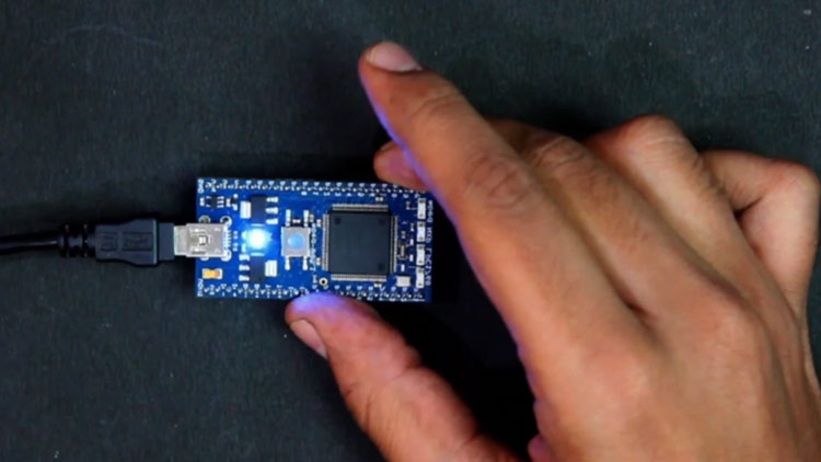
Connect the development board with the computer using the USB cable provided in the box. As you connect the status LED starts blinking and as soon as the connection gets stable it glows continuously as shown in the figure below.
How to get started with the MBED online IDE
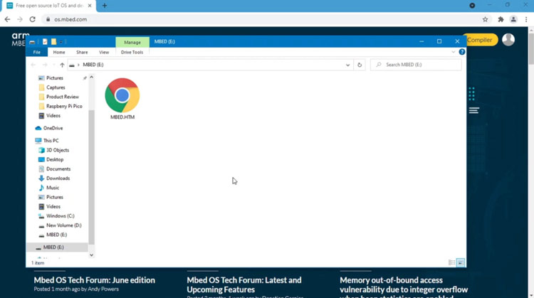
First, open http://os.mbed.com/. You can type this either on the search bar or. Open the new storage option named as MBED (_:) in your ‘This PC’. There you will find an MBED.htm file. Double clicking will take you to the webpage associated with your development board.
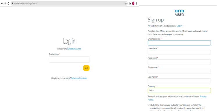
Click on the human silhouette at the top right corner of your screen and it will ask you to login.
If you don’t have an MBED account, register yourself. Click on Create an account and provide the credentials and register yourself so that you can start programming. If you already have an account, login to your account using your credentials.
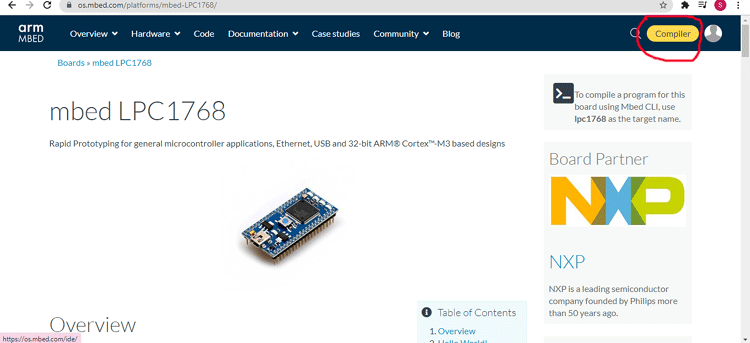
Once logged in, click on the compile button present at the top right of your page.
A new compiler page will open, in the page click on the right side to select a development board. The first thing is to select the development board. You need to select it before compiling your program so that it is compatible with the board. If your board is not visible in the new pop-up window, then click on ‘Add Board’. It will take you to a page containing all the compatible platforms. Select the board of your choice.
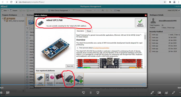
A new page will open with all the MBED compatible development board present in the page, select your platform by double clicking on it. A new page of the platform will open, go down in the page and you will see a button named ‘Add to your Mbed Compiler’. Clicking on the button will add it to your compiler. Now select your platform.
Click on the import button on top left of your screen and you will be taken to a page where you can import programs or libraries
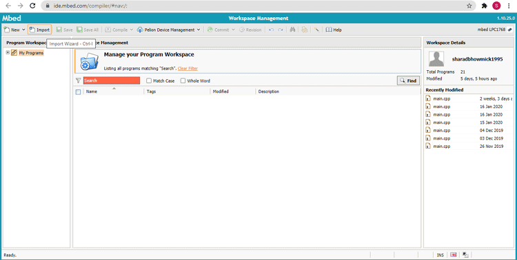
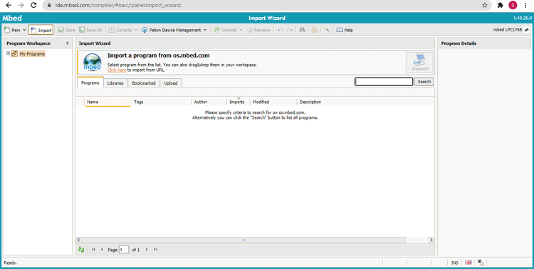
You can also go and select the libraries from the menu, the most common library is mbed.h. Or select a code from the repository.
Type name of the program in search bar> Double click on the file > Click on import
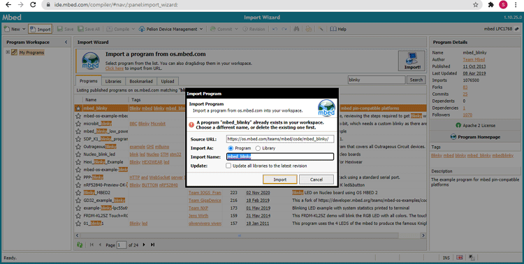
The program gets imported to your work space. Open the .cpp file and make in the necessary changes in the program to change any parameter.
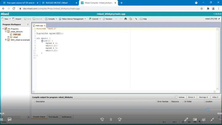
Then click the compile button and a binary file gets downloaded to your pc.
Open the download folder > copy the downloaded file> paste it to your mbed flash drive.
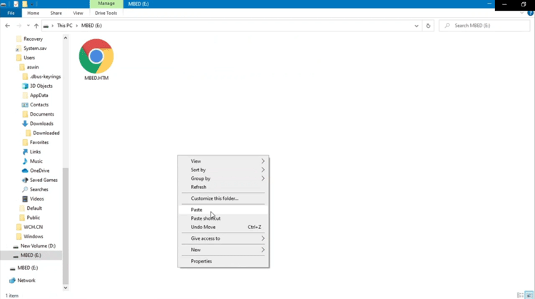
Your file gets uploaded to your microcontroller. The LED keeps blinking till the file is being uploaded, once uploaded, it starts glowing continuously.
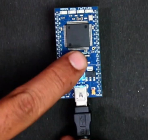
Press the reset button will upload the binary into the LPC1768. Your file has been uploaded. Your specified LED starts blinking as per your code.
Conclusion
This is a very interesting and versatile board with support for a lot of sensors and peripherals. It is a development board that is easy to program. A strong online community and loads of existing examples make it a very attractive option.

