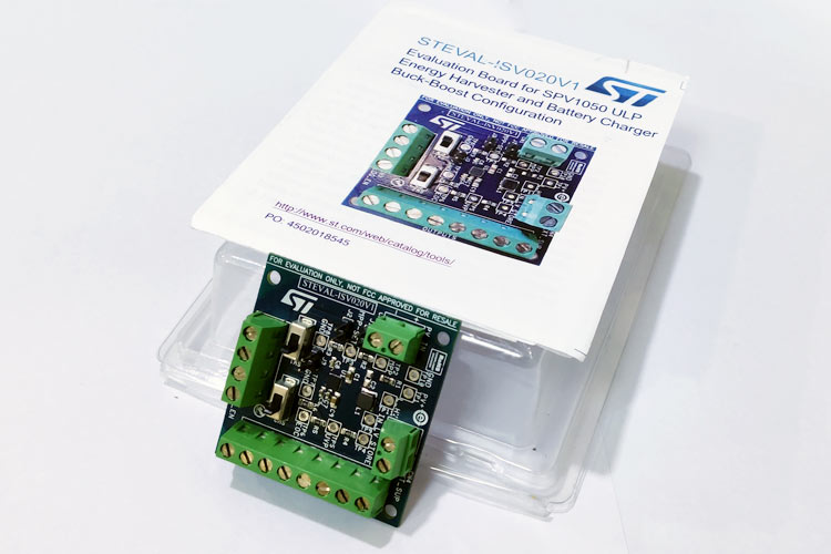
If you are looking for a solution to make a standalone system that doesn't require replacing battery, then STEVAL–ISV020V1 Evaluation Board from STMicroelectronics can be the ideal solution. This board consists of the SPV1050 Energy Harvesting IC that is capable of utilizing the energy harvested by solar panel or Thermo Electric Generator TEG to charge a battery. In this article, I will be explaining its features, functionality and power output along with some potential application. Also, I will be testing this board with different inputs in various lighting conditions to charge different energy storage devices to show it in action. Later in the article, we will be analyzing the derived data to see if this board can be used with any existing setup or not.
What is Energy Harvesting?
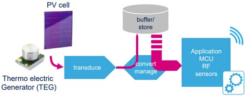
Energy harvesting is a method of harnessing power from external sources such as wind, solar, motion, or even from Wi-Fi signals, to be used for small and portable applications such as wireless sensors, automation, or projects such as wearable electronics, IoT or smart home applications that require wireless sensor network. It can be used for powering a device or be used for storing energy in a battery or capacitor for future use. A simple diagram showing how energy harvesting is done is shown below.
SPV1050 Energy Harvesting and Battery Charging IC
The Steval-ISV020V1 is an evaluation board that features a SPV1050, an ultra-low power energy harvester. The main feature of this board is that it can charge different battery chemistries by harnessing very low energies from solar panels or even Peltier Coolers also known as Thermo Electric Generators. What makes this board shine out is its ability to utilize miniscule amount of current and voltage produced by solar panels. The image of the board is shown below.
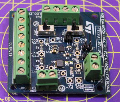
This board is capable of charging a cell even when the input has few microamps of current. The ability to charge a battery over a wide range of input voltage and current makes it a very useful device. The schematic of the board is shown below.
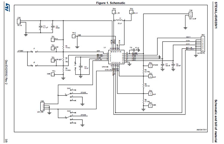
In the above schematics, the U1 denotes the SPV1050, here J1, J2, J3 Jumpers are used for enabling or disabling the MPPT. The CN2, 8-way screw connector is used for connecting the battery for getting the battery status signals. The 2, 5 pin male switches are used for controlling the LDO while the 4-way screw connector adjacent to it denotes the connector for LDOs load connection.
This low energy harvesting board can work on indoor PV or TEG (Peltier cooler). This evaluation board has a buck-boost configuration and has optimized system configuration to make SPV1050 work at higher efficiencies.
The board is capable of taking input voltages between 2.6V to 9V with ability to utilize current as low as 10uA. This large range makes the board capable of charging different battery chemistries such as Li-ion, NiMH, solid state batteries or even super capacitors.
How to use this board with higher powered solar panels or TEG?
With alteration in passive components, i.e. the input resistors and capacitors, it can be used with higher powered PV panels or even with a Thermo Electric generator. To charge different battery chemistries, we need to alter the settings of , Under Voltage Protection Threshold ( ) and End of Chage Voltage Threshold ( ) according to the required input and output. This can be done by changing few passive components in the board. By making the necessary changes, the operating range can be extended from 150mV to 18V, upto 100mA, down to 2.2V and upto 5.3V.
Key Features of Steval-ISV020V1:
- First startup at Vin = 2.6 V
- Input voltage working range:
- 150 mV > Vin > 18 V
- End of charge battery voltage: VEOC = 4.25 V
- Battery undervoltage protection: VUVP = 3.7 V
SPV1050: The energy harvesting IC
SPV1050 IC is the heart of the system. It is an ultra-low-power energy harvester with integrated battery charger. Capable of achieving high efficiency while having a small form factor which is critical for a remote sensing node, this IC employs a full-bridge DC-DC Buck-Boost converter topology, which makes it usable with different inputs such as photovoltaic (PV) cells or thermal energy generators (TEG). The availability of a maximum power point tracking algorithm (MPPT) can boost the energy harvested by 60%. The SPV1050 is available in a 5 x 5 mm, 20-lead QFN package and in die form. The image below shows the internal block diagram of the SPV1050 IC.
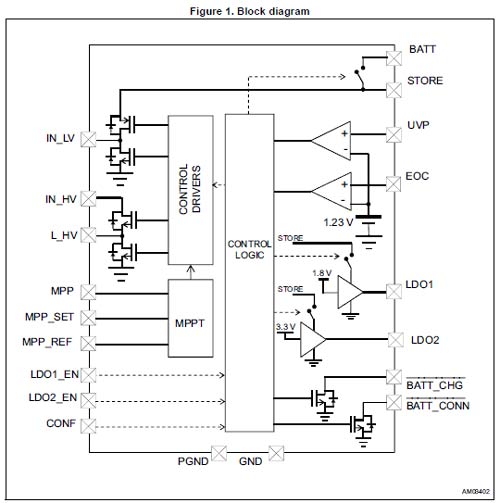
The MPPT functionality present in the SPV 1050 is programmable by a resistor input divider and allows maximizing the source power under any temperature and irradiance condition. The MPPT algorithm can be disabled by shorting the MPP-SET pin to the STORE pin, and by providing an external voltage to the MPP-REF pin.
Battery Charger
The IC has a battery charger circuit that improves the lifetime and safety of the battery, it controls an integrated pass transistor between the STORE and BATT pins and implements both the undervoltage (UVP) and the end-of-charge (EOC) protection thresholds.
Key Features of SPV1050:
- Transformerless thermoelectric generators and PV modules energy harvester
- High efficiency for any harvesting source
- Up to 70 mA maximum battery charging current
- Fully integrated buck-boost DC-DC converter
- Programmable MPPT by external resistors
- 2.6 V to 5.3 V trimmable battery charge voltage level (± 1% accuracy)
- 2.2 V to 3.6 V trimmable battery discharge voltage level (± 1% accuracy)
- Two fully independent LDOs (1.8 V and 3.3 V output)
- Enable/disable LDO control pins
- Battery disconnect function for battery protection
- Battery connected and ongoing charge logic
- open drain indication pins
Solar Panels used as Inputs
For showing the working of the energy harvester, I have used a solar panel from powerfilm, SP3-37 and another solar panel is a combination of 2 panels purchased from an ecommenrce website. 2 different inputs have been used to show the working of the module in both buck and boost configuration and to show how it works in different lighting conditions.
SP3-37
It belongs to the classic application series that are extremely flexible and meant for indoor usage for wireless electronics, wearables and remote applications. This specific solar panel doesn’t have an UV-stabilized surface, hence you should avoid long term outdoor usage. The image given below shows a SP3-37 alongside a Victorinox Champ multi utility knife. From the image, it can be clearly seen how thin and small this solar panel is.
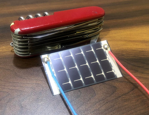
From the name itself, we can say that the solar panel gives an output of 3 Volts and the number 37 tells that it has a width of 37mm. It is a 1.1g solar panel that can be used in most low-powered application. The specifications of the solar panel is given below:
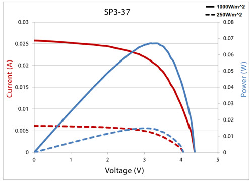
Max Output Power (Pmax) = 70mW
Max Output Current(Imax) = 22mA
Max Output Voltage (Vmax) = 3V
Short Circuit Current (Isc) = 28mA
Open Circuit Voltage (Voc) = 4.6V
The VI curve of this thin film solar panel is given below:
Connecting Wire to a SP3-37
To solder your SP3-37 flexible solar panel, heat your soldering iron tip and run over the silver part. Scrape off the upper plastic film with your hot soldering iron tip and you will observe that the plastic burns off creating a niche in your solar panel. Melt and deposit some soldering wire at the niche you just created by scraping off any remaining plastic. Finally, tin a wire and connect it to the solar panel into the location.
Dual Solar Panel Setup
The other solar panel used for testing is a combination of 2 panels with rating of 5.5V and 250mA. I ordered these solar panels from an e-commerce website. The description stated that it is a 1.2Watt monocrystalline solar panel. I’ve connected both the 1.2W panels in parallel to make a larger panel. Theoretically, the combined panel can give an output of over 2.6watts.
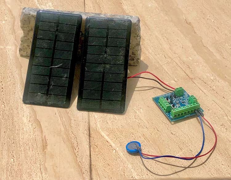
On testing the solar panel setup in the sun, the following data was achieved:
Open circuit voltage Voc = 5.5V
Short Circuit Current Isc = 280mA
The maximum power (PMAX, or sometimes written MPP) equation is given by multiplying the Open Circuit Voltage (VOC) and the short circuit current (ISC) together, it gives a rough estimate of the power, We also take the fill factor of Solar panel into consideration while calculating the PMAX. We cannot measure the fill factor without a load but it is typically around 0.7. PMAX is given by:
PMAX=Voc×Isc×FF
So the maximum power of this solar panel by our experiment is
PMAX=5.5×280mA×0.7 = 1.078 Watt
Testing the Energy Harvester
The maximum power (PMAX, or sometimes written MPP) equation is given by multiplying the Open Circuit Voltage (VOC) and the short circuit current (ISC) together, it gives a rough estimate of the power, We also take the fill factor of Solar panel into consideration while calculating the PMAX. We cannot measure the fill factor without a load but it is typically around 0.7. PMAX. It is denoted by:
PMAX=VOC×ISC×FF
Testing the SP3-37
The SP3-37 being flexible has inherited advantages as it makes it more appealing for wearable applications where appearance and aesthetics are paramount but on the downside, the efficiency is lower than the regular solar panel of similar dimensions.
SP3-37 with the Supercapacitor
The Open circuit voltage was 1.7V and the short circuit current was 30uA (51microwatts or 5.1*10^-6 W). In this condition, I have used a 1Farad, 5.5V supercapacitor with this setup. After 2 hours, the supercapacitor got charged by 0.137V that is 0.009385 Joules or 9.385mW. That is basically 1.6uW of energy every second. When this setup was kept outside in the patio but not directly facing the sun, the same setup was able to charge the supercapacitor to 2.78V from 0 in 3 hours, (around 3.9Joules of energy). It charged 1.85V in 2 hours (475.36uW or 39.5uW per second).
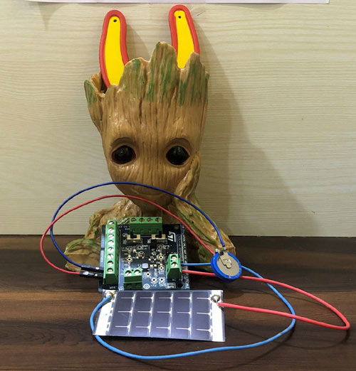
SP3-37 with the Battery
I tried charging the battery with the SP3-37 for several hours, but due to the low output from the solar panel, the battery could not get any substantial amount of charge, then I decided to stop testing this setup as it made no sense to continue testing with this setup.
Charging super capacitor with Dual solar panel
Charging the supercapacitor with the solar panel inside a moderately lit area and it charged the supercapacitor to 2.8V that is 19.6 J that is around 2.18 milliwatt per second. The higher energy is justifiable as the output power of this setup is much higher than the SP3-37. As shown in the figure, the output from the module was between 4.1-4.2V.
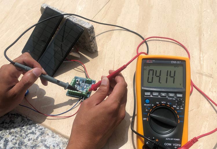
Dual Solar panel with Battery
I charged the battery with the solar panel in a moderately lit area and it charged the battery from 3.52V to 3.538 V in 90 minutes that corresponds to 21.6Joules (4milli watt per second) testing the setup again, it got charged by 60.48 Joules in 3 hours (from 3.538V to 3.552V in 3 hours) i.e. 5.6 milliwatt per seconds.
Keeping the dual solar panel setup in the patio, during the day time, but not directly facing the sun, it got charged by 970 Joules in 2 hours, i.e. about 135.5 milliwatt energy per second
Considering the battery to be 4.4Watt hour, this setup will be able to charge the battery from 0 to 100% in approximately 33 hours. It might not seem like a very efficient method but considering that it is a small portable setup, which is supposed to be clubbed with low powered standalone system, it makes sense. Below is the table of the analyzed data:
|
|
Super Capacitor |
|
Battery |
|
|
Placement |
Inside |
Outside |
Inside |
Outside |
|
Sp3-37 |
1.3uW/sec |
237uW/Sec |
- |
- |
|
Dual Solar panel |
2.1mW/sec |
- |
5.6mW/sec |
135.5mW/Sec |
|
|
|
|
|
|
Where and how it can be used?
We can use this board with ultralow power MCUs such as STM-32. A Node MCU board is capable of utilizing as low as 20uA current during its deep sleep mode. The node MCU can remain in the deep sleep mode for 72 minutes. But the power consumption can only be calculated based on the types of sensors used and frequency of data transmission required, thereafter, a suitable solar panel and battery system combination needs to be selected. An image of Node MCU is shown below.
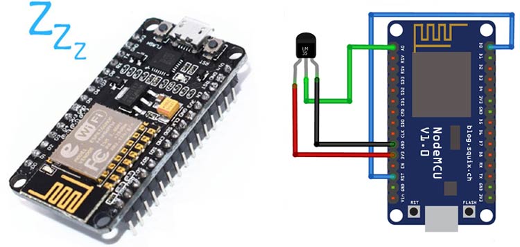
For Eg, a Node MCU utilizes 20uA in deep sleep mode and during transmission, requires an energy of 120-170mA. If we connect it with a LM35 temperature sensor which requires a 60uA of current, even our thin film SP3-37 setup with the supercapacitor, placed in a lowly lit area would be able to run the setup. This system can easily be used to power this setup sending data every few hours. The skeleton deep sleep sketch would look like:
- The ESP8266 connects to Wi-Fi
- The ESP8266 performs a task , here read the LM-35 data and publishes an MQTT message.
- Goes in the Deep Sleep Mode for a predefined period of time.
- After predefined time, the ESP8266 wakes up and the whole process is repeated over and over again.
Application
The ability to charge even with small amount of energy makes this board capable of being used in a plethora of applications. It can be used in all the standalone systems, requiring low power. The most appropriate application for this board is for wearable electronics, IoT devices, wireless sensing, smart home, weather monitoring station, etc.
Conclusion
Doesn’t matter whether you keep your harvesting module in a well-lit room or inside your calm and serene room, no matter how miniscule the amount of energy generated by your solar panel or TEG is, this module is capable of making the energy usable by storing it in the battery or in the super capacitor to be used later. It employs various techniques to condition the charge to keep your battery’s health great and its ability to charge different battery chemistry us just a cherry on the cake. So, this energy harvester module coupled with a solar panel will be able to generate enough energy for your low powered application. Although you might have to decide the sizing of the storage system and your harnessing solar panel, but rest assured it will be able to charge your system.


