What is a Counter?
A counter is a device which can count any particular event on the basis of how many times the particular event(s) is occurred. In a digital logic system or computers, this counter can count and store the number of time any particular event or process have occurred, depending on a clock signal. Most common type of counter is sequential digital logic circuit with a single clock input and multiple outputs. The outputs represent binary or binary coded decimal numbers. Each clock pulse either increase the number or decrease the number.
What is Asynchronous?
Asynchronous stands for the absence of synchronization. Something that is not existing or occurring at the same time. In computing or telecommunication stream, Asynchronous stands for controlling the operation timing by sending a pulse only when the previous operation is completed rather than sending it in regular intervals.
Asynchronous Counter
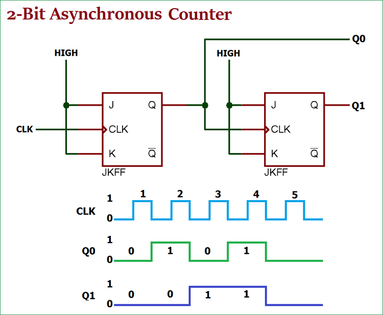
Now we understood that what is counter and what is the meaning of the word Asynchronous. An Asynchronous counter can count using Asynchronous clock input. Counters can be easily made using flip-flops. As the count depends on the clock signal, in case of an Asynchronous counter, changing state bits are provided as the clock signal to the subsequent flip-flops. Those Flip-flops are serially connected together, and the clock pulse ripples through the counter. Due to the ripple clock pulse, it’s often called a ripple counter. An Asynchronous counter can count 2n - 1 possible counting states.
Asynchronous Truncated Counter and Decade Counter
As there is a maximum output number for Asynchronous counters like MOD-16 with a resolution of 4-bit, there are also possibilities to use a basic Asynchronous counter in a configuration that the counting state will be less than their maximum output number. Modulo or MOD counters are one of those types of counters. The configuration made in such a way that the counter will reset itself to zero at a pre-configured value and has truncated sequences.
So, if a counter with the specific number of resolutions (n-bit Resolution) count up to is called as full sequence counter and on the other hand, if it is count less than the maximum number, is called as a truncated counter.
To get the advantage of the asynchronous inputs in the flipflop, Asynchronous Truncated counter can be used with combinational logic.
Modulo 16 asynchronous counter can be modified using additional logic gates and can be used in a way that the output will give a decade (divided by 10) counter output, which is useful in counting standard decimal numbers or in arithmetic circuits. This type of counters called as Decade Counters.
Decade Counters requires resetting to zero when the output reaches a decimal value of 10.
If we count 0-9 (10 steps) the binary number will be –
| Number Count | Binary Number | Decimal Value |
| 0 | 0000 | 0 |
| 1 | 0001 | 1 |
| 2 | 0010 | 2 |
| 3 | 0011 | 3 |
| 4 | 0100 | 4 |
| 5 | 0101 | 5 |
| 6 | 0110 | 6 |
| 7 | 0111 | 7 |
| 8 | 1000 | 8 |
| 9 | 1001 | 9 |
So, When the output reaches to 1001 (BCD = 9), the counter needs to be reset. To reset the counter, we need to feed this condition back to the reset input. Counter which counts 0000 (BCD = 0) to 1001 (BCD = 9), is referred as BCD or Binary-coded Decimal counter.
Timing Diagram of Asynchronous Decade Counter and its Truth Table

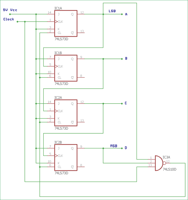
In the above image, a basic Asynchronous counter used as decade counter configuration using 4 JK Flip-Flops and one NAND gate 74LS10D. The Asynchronous counter count upwards on each clock pulse starting from 0000 (BCD = 0) to 1001 (BCD = 9). Each JK flip-flop output provides binary digit, and the binary out is fed into the next subsequent flip-flop as a clock input. In the final output 1001, which is 9 in decimal, the output D which is Most Significant bit and the Output A which is a Least Significant bit, both are in Logic 1. These two outputs are connected across 74LS10D’s input. When the next clock pulse is received, the output of 74LS10D reverts the state from Logic High or 1 to Logic Low or 0.
In such a situation when the 74LS10D change the output, the 74LS73 J-K Flip-flops will get reset as the output of the NAND gate is connected across 74LS73 CLEAR input. When the flip-flops reset, the output from D to A all became 0000 and the output of NAND gate reset back to Logic 1. With such configuration, the upper circuit shown in the image became Modulo-10 or a decade counter.
The Truth table of Decade counter is shown in the next table-
| Clock Pulse | Decimal Value | Output - D | Output – C | Output – B | Output - A |
| 1 | 0 | 0 | 0 | 0 | 0 |
| 2 | 1 | 0 | 0 | 0 | 1 |
| 3 | 2 | 0 | 0 | 1 | 0 |
| 4 | 3 | 0 | 0 | 1 | 1 |
| 5 | 4 | 0 | 1 | 0 | 0 |
| 6 | 5 | 0 | 1 | 0 | 1 |
| 7 | 6 | 0 | 1 | 1 | 0 |
| 8 | 7 | 0 | 1 | 1 | 1 |
| 9 | 8 | 1 | 0 | 0 | 0 |
| 10 | 9 | 1 | 0 | 0 | 1 |
| 11 | 0 | 0 | 0 | 0 | 0 |
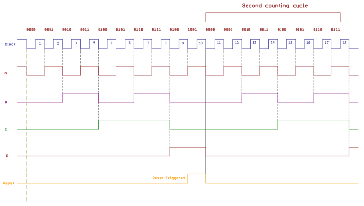
The below image is showing the timing diagram and the 4 outputs status on the clock signal. The reset pulse is also shown in the diagram.

Creating the Asynchronous Counter, Example, and Usability
We can modify the counting cycle for the Asynchronous counter using the method which is used in truncating counter output. For other counting cycles, we can change the input connection across NAND gate or add other logic gates configuration.
As we discussed before, that the maximum modulus can be implemented with n numbers of flip-flops is 2n . For this, if we want to design a truncated asynchronous counter, we should find out the lowest power of two, which is either greater or equal to our desired modulus.
For example, if we want to count 0 to 56 or mod – 57 and repeat from 0, the highest number of flip-flops required is n = 6 which will give maximum modulus of 64. If we choose fewer numbers of flip-flops the modulus will not be sufficient to count the numbers from 0 to 56. If we choose n = 5 the maximum MOD will be = 32, which is insufficient for the count.
We can cascade two or more 4-bit ripple counter and configure each individual as “divided by 16” or “divided by 8” formations to get MOD-128 or more specified counter.
In the 74LS segment, 7493 IC could be configured in such way, like if we configure 7493 as “divided by 16” counter and cascade another 7493 chipsets as a “divided by 8” counter, we will get a “divide by 128” frequency divider.
Other ICs like 74LS90 offer programmable ripple counter or divider that can be configured as a divide by 2, divide by 3 or divide by 5 or other combinations as well.
On the other hand, 74LS390 is another flexible choice which can be used for large divide by a number from 2 to 50,100 and other combinations as well.
Frequency Dividers
One of the best uses of the asynchronous counter is to use it as a frequency divider. We can reduce high clock frequency down to a usable, stable value much lower than the actual high-frequency clock. This is very useful in case of digital electronics, timing related applications, digital clocks, interrupt source generators.
Suppose we are using classic NE555 timer IC which is a Monostable/Astable Multivibrator, running at 260 kilohertz and the stability is +/- 2 %. We can easily add a “Divided by 2” 18-bit ripple counter and get 1 Hz stable output which can be used for generating 1-second of delay or 1-second of the pulse which is useful for digital clocks.

This is a simple circuit to produce stable frequency or timing from an unstable source by dividing the frequency using ripple counter. More precise crystal oscillators can produce precise high frequency other than the signal generators.
Advantages and Disadvantages of Asynchronous Counter
Asynchronous counters can be easily built using Type D flip-flops. They can be implemented using “divide by n” counter circuit, which offers much more flexibility on larger counting range related applications, and the truncated counter can produce any modulus number count.
But, despite those features, Asynchronous counter offer some limitations and disadvantages.
While using the Asynchronous counter, an additional re-synchronizing output flip-flops required for resynchronizing the flipflops. Also, For the truncated sequence count, when it is not equal to , extra feedback logic is needed.
When counting a large number of bit, due to the chain system, propagation delay by successive stages became too large which is very difficult to get rid off. In such a situation, Synchronous counters are faster and reliable. There are also counting errors in Asynchronous Counter when high clock frequencies are applied across it.


