A transformer is a widely used device in the electrical and electronics domain. It is an electromagnetic device which follows the basic principle of electromagnetism discovered by Michael Faraday. We have covered Transformer construction and operation in detail in the previous tutorial. Here we will cover different types of transformers used in different types of applications. However, all types of transformers follow the same principles, but they have different construction methods. And with a little bit of effort, you can also build your own transformer, but while building the transformer one should always follow transformer protection techniques.
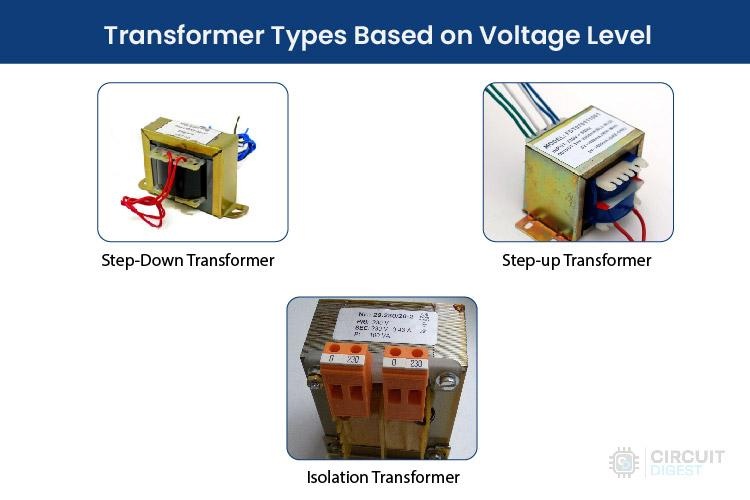
Transformer Types Based on Voltage Level
A Transformer can have multiple types of construction. The transformer does not have any electrical connection from one side to another; still, the two electrically independent coils can conduct the electricity by electromagnetic flux. A transformer can have multiple coils or windings on the primary side as well as on the secondary side. In several cases, multiple primary sides, where two coils are connected in series, are often called a center tapped. This center-tapped condition can also be seen on the secondary side.
Transformers can be constructed in a way that it can convert the voltage level of the primary side to the secondary side. Depending on the voltage level, the transformer has three categories. Step Down, Step Up and Isolation Transformer. For the Isolation transformer, the voltage level is the same for both sides.
1. Step-Down Transformer
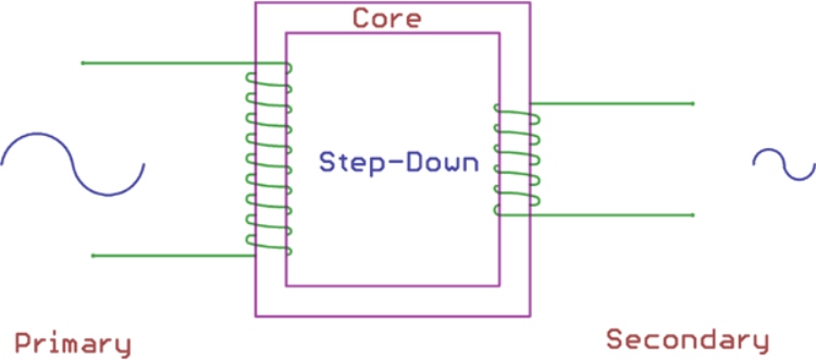
Step-down Transformer is used in both Electronics and Electrical domains. A step-down transformer converts the primary voltage level to a lower voltage across the secondary output. This is achieved by the ratio of primary and secondary windings. For step-down transformers, the number of windings is higher across the primary side than the secondary side. Therefore, the overall winding ratio of primary and secondary always remains more than 1.
In electronics, many applications run on 5V, 6V, 9V, 12V, 24V or in some cases 48V. To convert the single-phase power outlet voltage 230V AC to the desired low voltage level, Step-down transformers are required. In instrumentation as well as in many electrical types of equipment, a Step-Down transformer is the primary requirement for the Power section. They are also used in power adapters and cell phone charger circuits.
In electrical, step-down transformers are used in electrical distribution system which works on very high voltage to ensure low loss and cost-effective solutions for long-distance power delivery requirements. To convert the high voltage to a low voltage supply line, a step-down transformer is used.
2. Step-Up Transformer
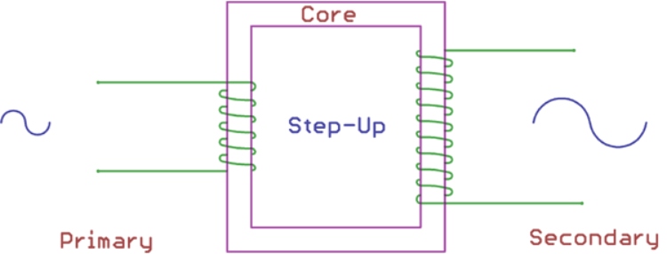
The step-up transformer is exactly the opposite of the step-down transformer. The step-up transformer increases the low primary voltage to a high secondary voltage. Again, it is achieved by the ratio of primary and secondary winding ratio. For the Step-Up transformer, the ratio of the primary winding and the Secondary winding remains less than 1. That means the number of turns in the secondary winding is higher than in the primary winding.
In electronics, step-up transformers are often used in stabilizers, inverters etc where low voltage is converted to a much higher voltage.
A step-up transformer is also used in Electrical power distribution. High voltage is required for power distribution-related applications. A step-up transformer is used in the grid to step up the voltage level before the distribution.
3. Isolation Transformer
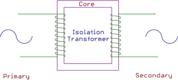
The isolation transformer does not convert any voltage levels. The Primary voltage and the secondary voltage of an isolation transformer always remain the same. This is because the primary and the secondary winding ratio is always equal to 1. That means the number of turns in primary and secondary winding is the same in the isolation transformer.
The isolation transformer is used to isolate the primary and secondary. As discussed previously, the transformer does not have any electrical connections between primary and secondary, it is also used as an isolation barrier where the conduction happens only with the magnetic flux. It is used for safety purposes and to cancel noise transfer from primary to secondary or vice-versa.
Transformer Types Based on Core material
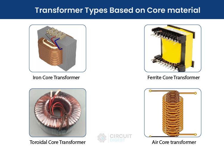
The transformer transfers the energy by conducting electromagnetic flux through a core material. Different core materials produce different flux densities. Depending on the core materials, several types of transformers are used in the power and electronics domain.
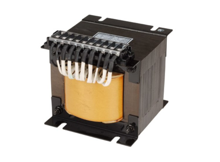
1. Iron Core Transformer
The iron core transformer uses multiple soft iron plates as the core material. Due to the excellent magnetic properties of iron, the flux linkage of the iron core transformer is very high. Thus, the efficiency of the iron core transformer is also high.
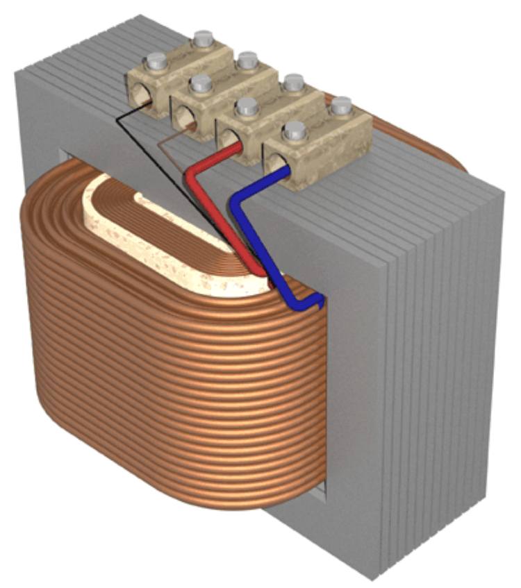
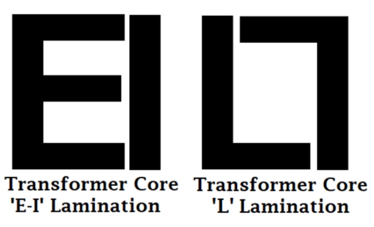
The soft iron core plates can be available in multiple shapes and sizes. The coils of the primary and secondary are wound or wrapped on a coil former. After that, the coil former is mounted in soft iron core plates. Depending on the core size and shape, a different type of core plate is available in the market. A few common shapes are E, I, U, L, etc. The iron plates are thin, and multiple plates are bunched together to form the actual core. For example, E-type cores are made with thin plates with the look of the letter E.
Iron core transformers are widely used and usually heavier in weight and shape.
2. Ferrite Core Transformer
A ferrite core transformer uses a ferrite core due to high magnetic permeability. This type of transformer offers very low losses in the high-frequency application. Due to this, ferrite core transformers are used in high-frequency applications such as in switch mode power supply (SMPS), RF-related applications, etc.
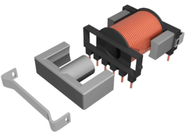
Ferrite core transformers are available in different shapes, and sizes depending on the application requirement. It is mainly used in electronics rather than electrical applications. The most common shape in the ferrite core transformer is the E core.
3. Toroidal Core Transformer
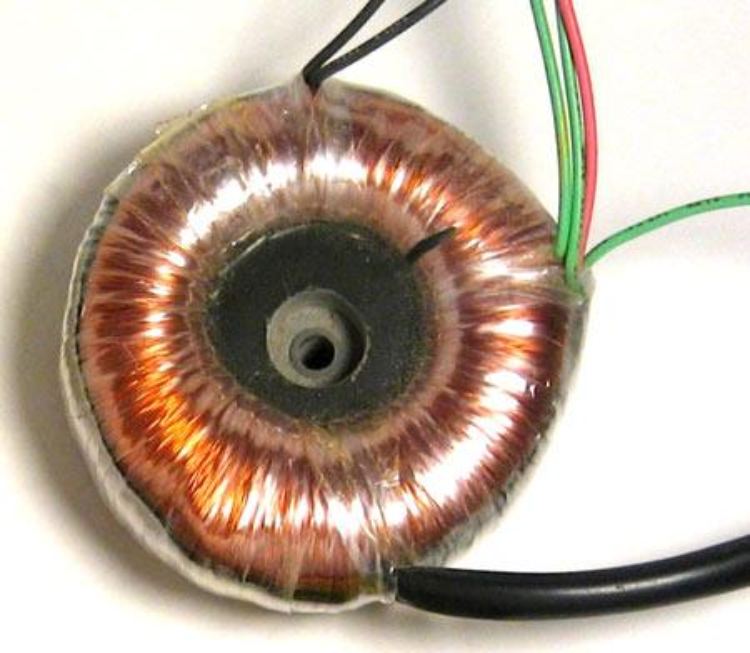
The toroidal core transformer uses toroid-shaped core material, such as iron core or ferrite core. Toroids are ring or doughnut-shaped core materials and are widely used for superior electrical performance. Due to the ring shape, the leakage inductance is very low and offers very high inductance and Q factors. The windings are relatively short, and their weight is much less than traditional, same-rating transformers.
4. Air Core Transformer
The Air Core transformer does not use any physical magnetic core as the core material. The flux linkage of the air-core transformer is made entirely using the air.
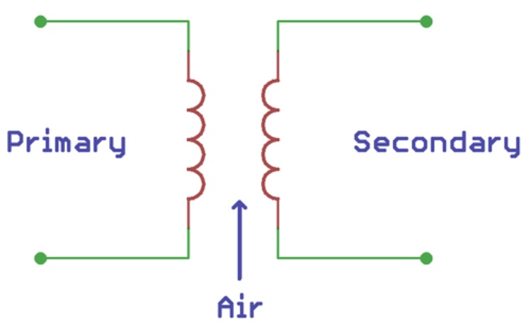
In an air core transformer, the primary coil is supplied with alternating current which produces an electromagnetic field around it. When a secondary coil is placed inside the magnetic field, as per the Faraday law of induction, the secondary coil is induced with a magnetic field which is further used to power the load.
However, air core transformer produces low mutual inductance compared to physical core material such as iron or ferrite core.
It is used in portable electronics as well as radiofrequency-related applications. Due to the absence of physical core material, it is very light in terms of weight. Properly tuned air-core transformers are also used in wireless charging solutions, where the primary windings are constructed inside the charger and the secondary windings are situated inside the targeted device.
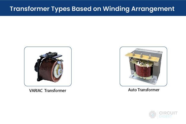
Transformer Types Based on Winding Arrangement
The transformer can be classified using winding orders. One of the popular types is Auto Winding Transformers.
Auto Winding Transformer
Till now, the primary and secondary winding is fixed but in the case of an auto-winding transformer, the primary and the secondary coil can be connected in series and the center-tapped node is movable. Depending on the centre-tapped position, the secondary voltage can be varied.
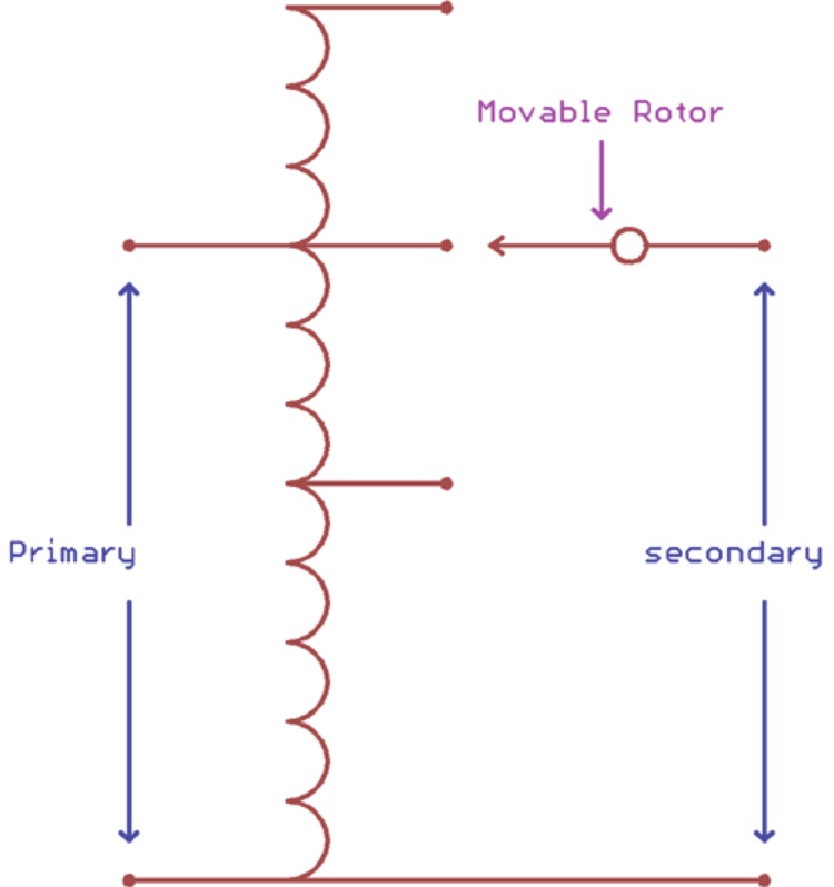
The auto is not the short form of Automatic; rather it is to notify the self or single coil. This coil forms a ratio which consists of two parts, primary and secondary. The position of the center tap node determines the primary and secondary ratio thus varying the output voltage.
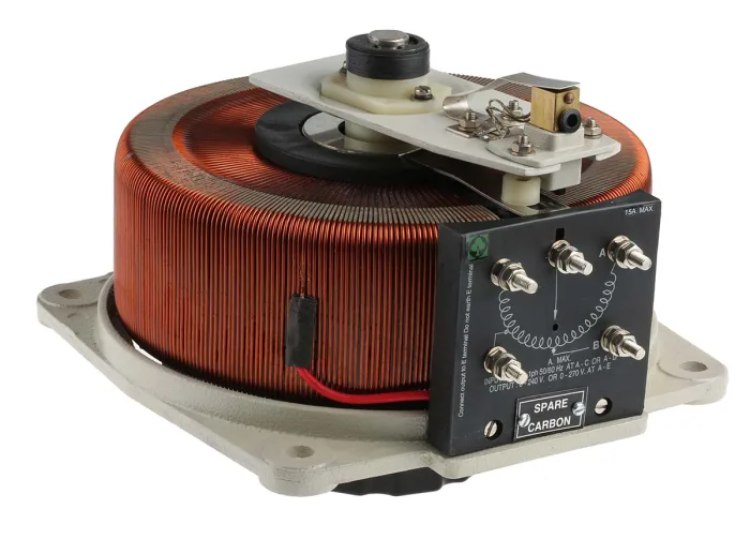
The most common use is the VARIAC, an instrument to produce variable AC from a steady AC input. It is also used in Power transmission and distribution-related applications where the high-voltage lines need to be changed frequently.
You can also find them with multiple tapping's instead without any moving parts. From these types of transformers, you can get different voltages by using different voltage tapping's. This type of transformer is commonly used in voltage stabilizers, UPS and inverters, and the different tapping's are selected using power relays.
Types of Transformers Based on Usage
There are several types of transformers also available that work in a specific domain. In both the electronics and electrical sectors, several dedicated transformers are used as step-down or step-up transformers based on the application. So, the transformers can be classified as below based on usage:
1. Power Domain
- Power Transformer
- Measurement Transformer
- Distribution Transformer
2. Electronics Domain
- Pulse Transformer
- Audio Output Transformer
- Current Transformer
- Voltage transformers
- RF transformers
1. Transformers used in Power Domain
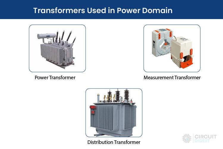
In Electrical, the Power domain deals with power generation, measurement, and distribution. However, it is a very large field where transformers are an essential part of accommodating safe power conversion and successful power delivery to the substation and to the end users.
The transformers which are used in the power domain can be both outdoor and indoor but mostly outdoor.
(a) Power Transformer
Power Transformers are larger in size and used to transfer the energy to the substation or the public electricity supply. This transformer acts as a bridge between the power generator and the primary distribution grid. Depending on the Power rating and specification, Power transformers can further be classified into three categories: small power transformers, Medium Power transformers, and large power transformers. The rating can be more than 30KVA to 500-700KVA or in some cases can be equal to or more than 7000KVA for a small, rated power transformer. The medium-rated power transformer can be up to 50-100 MVA whereas large power transformers are capable of handling more than 100MVA.
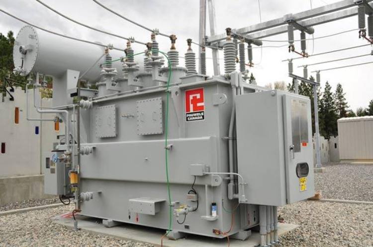
Due to very high-power generation, the construction of a power transformer is also critical. The construction includes solid insulating peripherals and well-balanced cooling system. The most common power transformers are filled with oils.
The main principle of the power transformer is to convert the Low voltage high current to a high voltage low current. This is required to minimize the power loss in the power distribution system.
Another important parameter for the Power transformer is the phase availability. Typically, Power transformers work in three-phase systems, but in some cases, Single-phase small power transformers are also used. Three-phase power transformers are more costly and efficient than single-phase power transformers.
(b) Measurement Transformer
A measurement transformer is often referred to as an instrument transformer. This is another commonly used measurement instrument in the power domain. A measurement transformer is used to isolate the main power and convert the current and voltage in a smaller ratio to its secondary output. By measuring the output, the Phase, Current and Voltage of the actual power line can be measured.
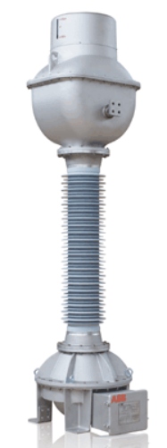
The above image shows the construction of the current transformer.
(c) Distribution Transformer
This is used in the last phase of the power distribution system. Distribution transformers are step-down transformer, which converts High grid voltage to the end customer's required voltage, 110V or 230V. It can also be a single phase or three phases.
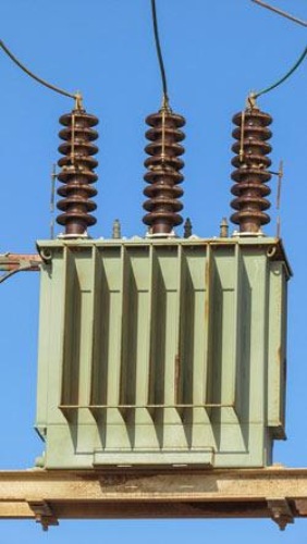
Distribution transformers can be smaller in shape as well as bigger, depending on the conversion capacity or ratings.
Distribution transformers can be further categorized based on the type of insulation they use. It can be a dry type or can be liquid-immersed. It is made using laminated steel plates mostly constructed in C shape as a core material.
Distribution transformer also has a different type of classification based on the location it is used. The transformer can be mounted on a utility pole, if so, it is called a pole-mounted distribution transformer. It can be placed inside of an underground chamber, mounted on a concrete pad (pad-mounted distribution transformer) or inside an enclosed steel box.
Generally, distribution transformers have a rating of less than 200kVA.
2. The Transformer used in Electronics Domain
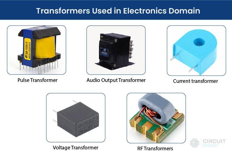
In electronics, various small miniature transformers are used which can be PCB mounted or can be fixed inside the small product enclosure.
(a) Pulse Transformer
Pulse transformers are one of the most used PCB-mounted transformers that produce electrical pulses in a constant amplitude. It is used in various digital circuits where pulse generation is needed in an isolated environment. Therefore, the pulse transformers isolate the primary and secondary and distribute primary pulses to the secondary circuit, often digital logic gates or drivers.
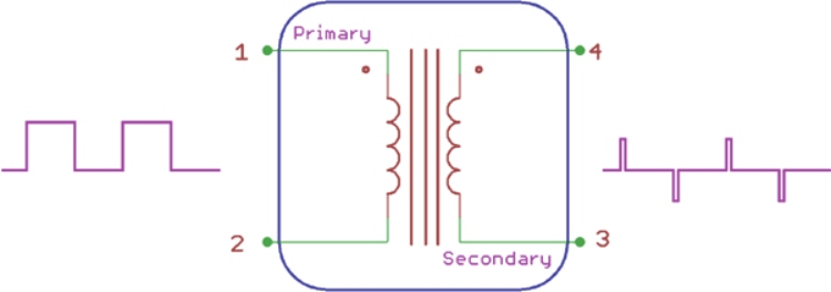
Properly constructed pulse transformers should need proper galvanic isolation as well as small leakage and stray capacitance.
(b) Audio Output Transformer
An Audio Transformer is another commonly used transformer in the electronics domain. It is specially used in audio-related applications where impedance matching is required. An audio transformer balances the amplifier circuit and loads, typically a loudspeaker. The audio transformer can have multiple primary and secondary coils, separated or center tapped.
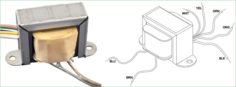
So, we have covered various kinds of transformer, other than that there are some other special purpose transformers but they are out of scope of this article.
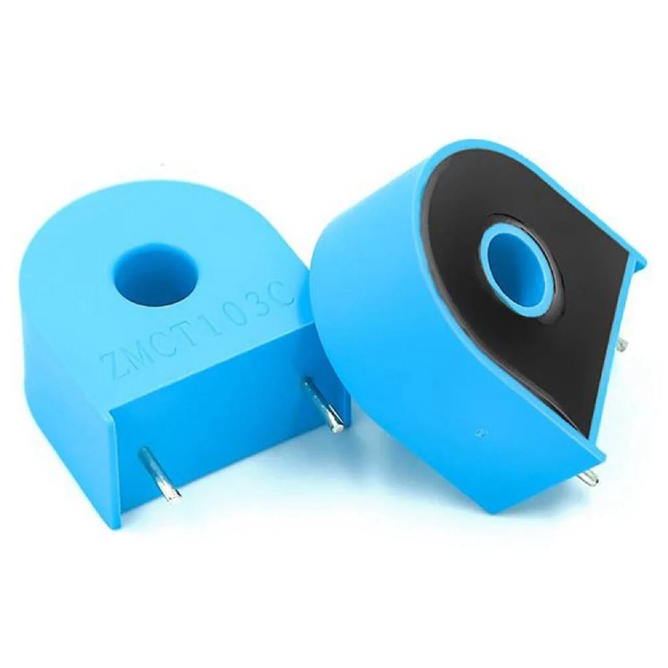
(C) Current Transformer
Just like in the power domain, we also have measurement or instrumentation transformers in the electronic domain. One of them is the current transformer, also known as CT. As the name suggests the current transformers are used to measure AC current. Typically, the current transformers will only have one or very few turns in the primary winding. This primary winding can be of either a single turn, a coil of heavy-duty wire wrapped around the core or just a conductor or bus bar placed through a central hole. Most of the time the Ct will only have a secondary winding on a core material, and the power line wire going through the hole of the core will act as the primary winding.
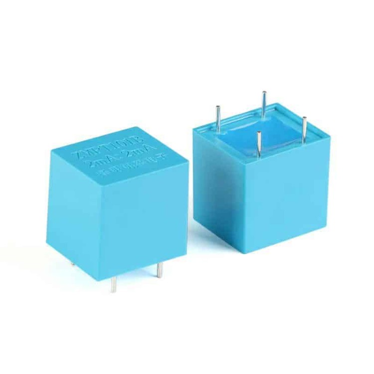
(D) Voltage Transformer
As the name suggests, the voltage transformers are used to measure the AC voltage. These are basically just a step-down transformer, with very little output current capabilities. They will step down the voltage to a level which can be measured using microcontrollers or such. They are available in many different form factors. The most popular voltage transformer among the DIY community is the ZMPT101B.
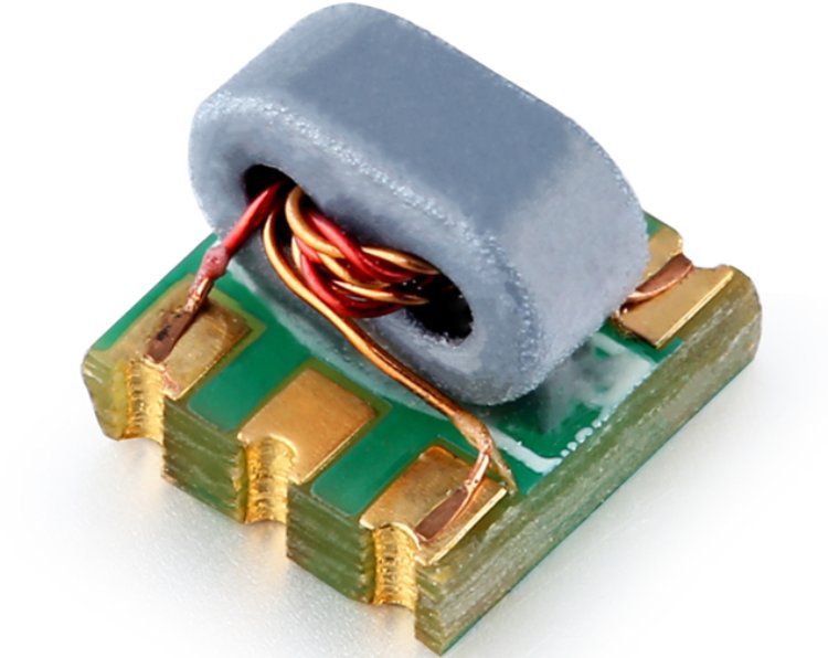
(E) RF Transformers
The RF transformers are typically used in radio and communication equipment. They are used for their ability to transfer electrical energy between circuits while maintaining impedance matching, isolation, and signal integrity at high frequencies. The RF transformers are normally designed to operate over specific frequency ranges and to minimize loss and distortion. They are typically manufactured using specialized core materials like ferrite or powdered iron.