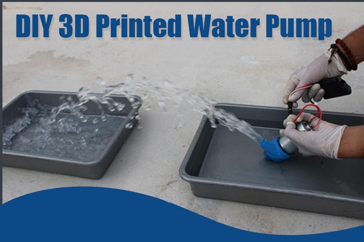
Hello guys, In this project we will see about making a DIY water pump using a generic motor 775. It's a fun and useful DIY project that can be easily implemented with basic tools and materials. The project does not require any kind of higher expertise in the domain.
The water pump device can be used for various purposes such as creating projects like firefighter bots, hydropower generators, Rainwater harvesting, and much more. Its versatility opens up a wide range of possibilities for various projects.
This project involves designing a powerful water pump using 3D printing technology. We will provide the design files and step-by-step instructions to guide you through the process. We will learn more about assembling procedures, connections, and project requirements. Also, we will see the technical specifications of the components and the working functionality of the water pump.
Components Required for Water Pump
- RS-775 DC motor(12v-24volt)
- 3D-Printed Structure Set (including impeller)
- Bolts or Screws
- 12-volt Power Source
- Rubber piece for insulation
- Marker and compass
Casing Required for Water Pump
We are going to use 3D-printed casing for our DIY water pump. These are enough strong and durable to withstand the pressure of water and the vibration of the motor. The ability to create intricate and customized designs, coupled with the advantages of lightweight construction, enhanced durability, and improved heat dissipation, make 3D-printed casings an attractive option for efficient water flow systems.
We are here using two types of casing i.e., Removable and Non-removable(permanent).
The mechanism of working a water pump is all about the centrifugal force generated due to the torque applied by the motor, keeping all this mechanism in mind, the 3d designs were created. It will be easy for you to print the 3d designs by yourself, as I am sharing the 3D-created design files. You can download that file from the below links.
If you are well aware of the process of 3D printing and you have 3D printers, then it will be a cost-effective & easy task. Otherwise, you can get online 3D printing services at affordable prices just by sending the STL file of your design.
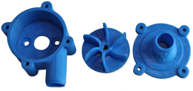
Removable Casing: It is a type of casing where we remove the motor whenever it is not needed because it uses the Nut-bolt mechanism, making assembling and de-assembling easy. Its biggest advantage is using the same motor for other projects. Also, any blockage inside the casing set can be easily cleaned.
The STL design file includes Outer Casing and Impeller designs which can be downloaded using the Link.
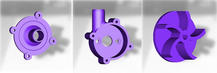
After 3d-printing, our structure is looking as below Image.
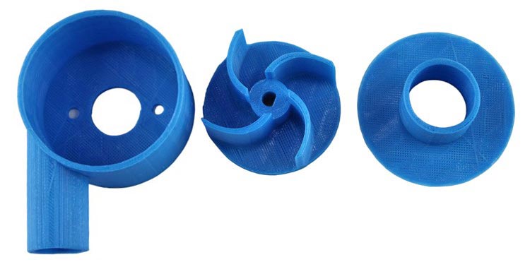
Non-removable Casing: In this type of casing, the outer part is completely glued using Araldite after the proper fitting of the impeller. It is a permanent solution; we can’t remove the motor at all.
The STL design file can be downloaded using Link.

After 3D Printing, our structure is looking as below Image.
Assembly & Functioning
A centrifugal water pump is a mechanical device that circulates and moves water through pipes by creating force in one direction.
A water pump required basic few necessary components for work. Let’s study the included components and their functioning:
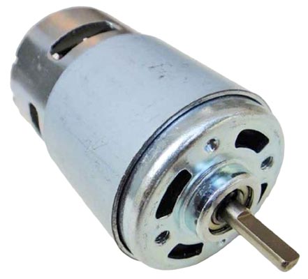
- 775 Motor: This commonly available DC motor offers high torque and power output. It runs on a 12-volt to 24-volt power supply. The motor/engine provides the necessary energy to rotate the impeller and generate the required pressure to move the water.
- Impeller: A fan-like component that will be attached to the motor shaft to create water movement. It consists of curved blades or vanes that are designed to push the water in a specific direction when the impeller spins.
- Housing/Casing: The housing or casing is the outer shell of the water pump, usually made of durable materials. It encloses all the internal components and provides support and protection. The 3D casing has two ports—an inlet and an outlet. The inlet port allows water to enter the pump, while the outlet port is where the pressurized water exits the pump.
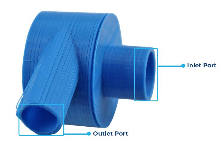
- Suction Pipe: The suction pipe is connected to the inlet port and is responsible for drawing water into the pump.
- Discharge Pipe: The discharge pipe is connected to the outlet port and carries the pressurized water away from the pump to the desired location.
- Power Supply: A suitable DC power supply to operate the motor (e.g., a 12V battery or power adapter).
- Screws, Nuts, and Bolts: For securing the motor, impeller, and other components.
Assembling and Connection of the Removable Water Pump
It is quite easy process & doesn’t take much time. Below Images give a brief Idea of the Required Components.
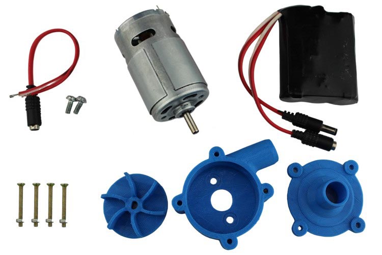
Let’s look at the step-by-step procedure:
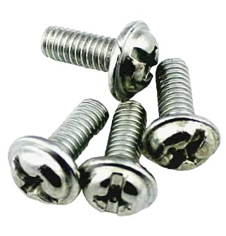
Screwed the back fittings of the case to the motor using an M4-10mm bolt shown in the image below.
- The “M” designation for metric screws indicates the outer diameter of the screw in millimeters, so for an M4 screw, the outer diameter is 4mm.
- The head is a standard star head and the length of the screw is 12mm.
After the proper fitting, the case will look like this:
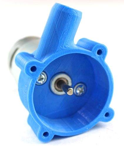
Take the impeller, whose center has a D-shaft hole to prevent slipping during high torque, and fix it to the motor shaft.
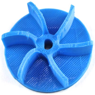
If your motor shaft is circled-shaped, then you can try to file the rotor shaft from the outer side to transform it into D-shape, or else if you can find it, you can directly purchase it. The motor 775 that I am using is also circled in shape, hence I used a Grinder machine to file its shaft.
After, the impeller fitting the structure will look like this:
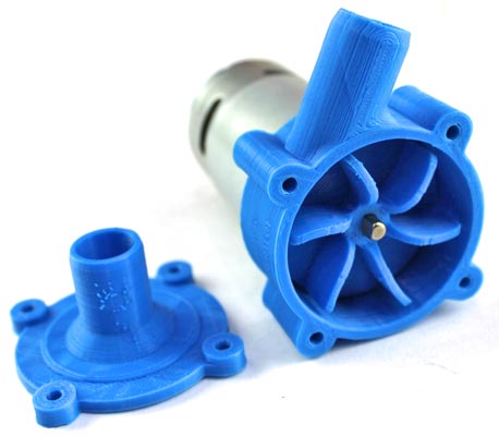
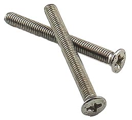
Now, attached the front side of the casing using the M3-30mm bolt, as shown in the below image.
- Outer Diameter is 3mm
- Length is 30mm
After all the fitting, the complete structure will look like the below image.
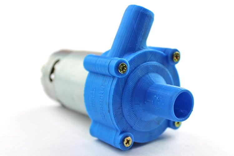
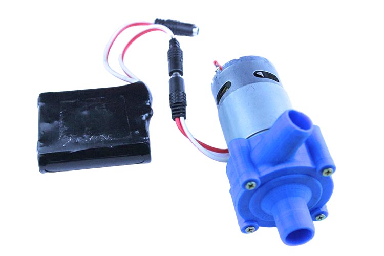
Take the DC female connector Jack soldered it to the two output pins of the motor.
Note: Be careful about the right polarity to set the clockwise spinning direction of the motor because the wrong direction spinning will not generate the water flow with full efficiency.
Connect the 12-volt battery supply (or you can use up to 24-volt), and see how the pump is working. We capture an image to demonstrate the pump.
Assembling and connection of the Non-Removable water pump
The necessary Required component is shown in the Below image. Some of the components are the same as in the case of Removable water pump. Hence, some of the steps are the same as previous one.
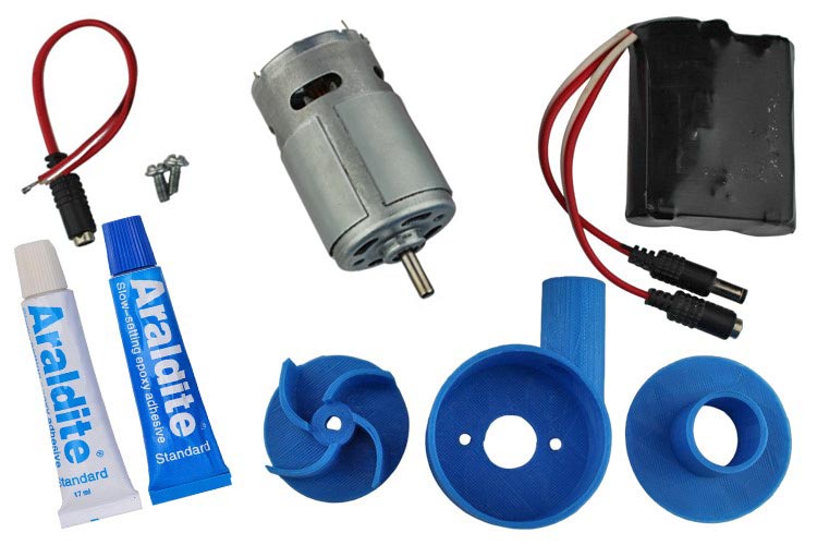
The same M4-10mm bolt is also used here to Screw the back fittings of the casing to the same 775 motor. For more details about the screws, you can refer to that step.
After the fittings, the casing will look like this:

Take the D-shaft impeller, and gently pushed to fix its hole into the D-shaft of the motor.
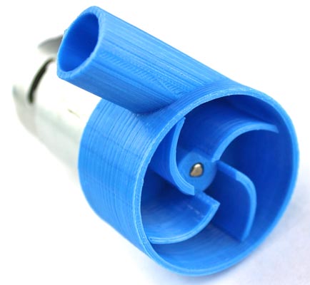
Apply the Araldite Glue at the round edges and fix the front side casing. Make sure the glue is properly set without any air leak spaces.
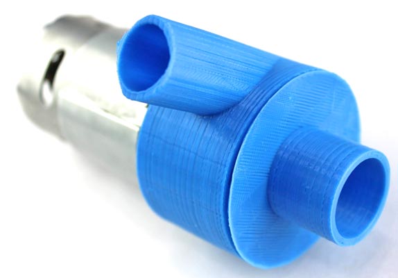
Soldered the DC female jack at the input pins of the motor by carefully observing the anti-clockwise spinning direction.
We connected the 12-volt battery and test the spinning direction and functionality of the motor.
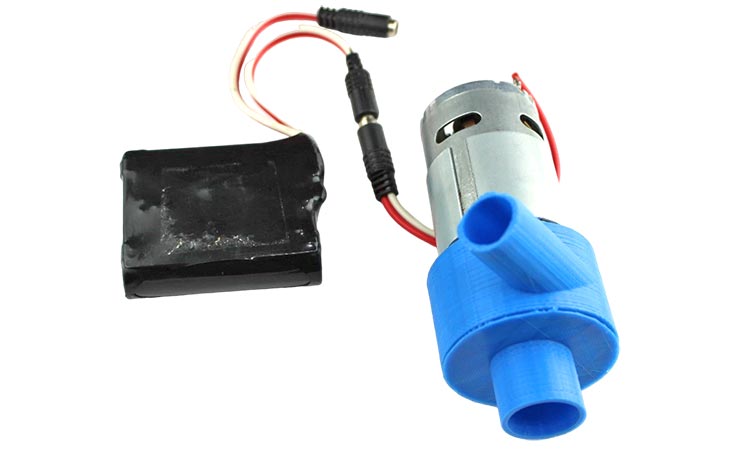
Demonstration & Testing
We have completed all pump fittings, remaining only the connection to a power source, and required some water-filled buckets.
As a power source, I am using a 12-volt Lithium-ion battery, you can also use a 12-volt adaptor, or else you can use up to a 24-volt power source.
Inlet/outlet suction Port sizes
- For Removable Casing: The external diameter should be 18mm (as per the STL file) for both inlet and outlet ports.
- For Non-Removable Casing: The inlet port should have an external diameter of 25mm whereas the outlet port has of diameter 20mm (as per the STL file).
The functioning of a water pump involves the following steps:
Priming: Before starting the pump, it needs to be primed to remove any air trapped inside the system. Priming involves filling the pump and suction pipe with water to create an airtight seal and ensure proper water flow.
Power Input: The motor or engine is started, providing the necessary rotational force to the driveshaft. We are using a 12-volt supply to power the motor.
Impeller Rotation: As the driveshaft rotates, it drives the impeller to spin rapidly inside the housing. The impeller's curved blades push the water outward from the center of rotation.
The rotation direction of the impeller is depending on the motor rotation direction. For, Removable pump it should be clockwise whereas for Non-removable it should be anticlockwise.
Water Intake: The rotating impeller creates a low-pressure zone at the inlet port, causing water to be drawn into the pump through the suction pipe. The water flows into the housing and towards the center of the impeller.
Impeller Action: The impeller blades propel the water radially outward with centrifugal force, increasing its pressure as it moves toward the outer edges of the impeller.
Water Discharge: The pressurized water exits the pump through the outlet port and flows into the discharge pipe. The pressure generated by the impeller's action allows the water to be transported to its intended destination.
Continuous Operation: The water pump continues to operate as long as the motor or engine is running, maintaining a steady flow of water and circulation throughout the system.
We learned the functioning and mechanism of the water pump and now it’s time to test and see the live working.
The Above GIF shows the live working of a Removable water pump whereas the below shows the working of a Non-removable pump.
The motor torque is enough to provide a sufficient water flow at a 12-volt power source but if You want to get high force torque, you can go with a 24-volt power source with a speed of up to 50-60 liters/min.
Hope you enjoyed the Project and learned something useful from it. If you have any questions, you can leave them in the comment section below.


