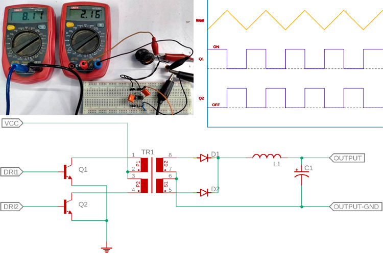
When it comes to working with power electronics, a DC-DC converter topology becomes very crucial for practical designs. There are mainly two types of major DC-DC conversion topologies available in power electronics, namely, the switching converter and the Linear converter.
Now from the law of conservation of energy, we know that energy cannot be created nor destroyed, but it only can be transformed. The same goes for switching regulators, the output power (wattage) of any converter is the product of voltage and current, a DC-DC converter ideally converts the voltage, or the current while the wattage is constant. An example could be the situation where a 5V output could provide 2A of current. Previously we have designed a 5V, 2A SMPS Circuit, you can check that out if that is something you are looking for.
Now consider a situation where we need to change it to a 10V output for a specific application. Now, if a DC-DC converter is used in this place, and the 5V 2A which is 10W output is constant, ideally the DC-DC converter will convert the Voltage to a 10V with a 1A current rating. This can be done using a boost switching topology where a switching inductor is constantly switched.
Another costly but useful method is to use a push-pull converter. A push-pull converter opens up lots of conversion possibilities, such as Buck, Boost, Buck-Boost, isolated, or even non-isolated topologies, also it is one of the oldest switching topologies used in power electronics that require minimum components to produce medium power outputs (Typically - 150W to 500W) with multiple output voltage. One needs to change the transformer winding for changing the output voltage in an isolated push-pull converter circuit.
However, all these features put out many questions in our minds. Like, how does a Push-pull converter work? What components are important to build a push-pull converter circuit? So, read along and we will find out all the necessary answers and in the end, we will be building a practical circuit for demonstration and testing, so let's get right into it.
Construction of a Push-Pull Converter
The name has the answer. Push and Pull have two opposite meanings of the same thing. What is the meaning of Push-Pull in layman's terms? The dictionary is saying that the word push means to move forward by using force to pass people or objects to move aside. In a push-pull DC-DC converter, the push defines pushing the current or feeding the current. Now, what pull means? Again, the dictionary says to exert force on someone or something to cause movement toward oneself. In the push-pull converter, it is again the current that is being pulled.
Thus, a push-pull converter is a type of switching converter where currents are constantly pushed into something and constantly pulled from something. This is a type of flyback transformer or an inductor. The current is constantly pushed and pulled from the transformer. Using this push-pull method, the transformer transfers flux to the secondary coil and provides some kind of isolated voltage.
Now, as this is a type of switching regulator, also as the transformer needs to be switched in such a way that the current needs to be pushed and pulled synchronously, for that we need some kind of switching regulator. Here, an asynchronous push-pull driver is required. Now, it is obvious the switches are made with different types of Transistors or Mosfets.
There are lots of push-pull drivers available in the electronics market that can be used immediately for push-pull conversation related work.
Few of such Driver ICs can be found in the below list:-
- LT3999
- MAX258
- MAX13253
- LT3439
- TL494
How Does a Push Pull Converter Work?
To understand the working principle of the push-pull converter, we have drawn a basic circuit which is a basic half-bridge push-pull converter, and its shown below, for the sake of simplicity, we have covered the half-bridge topology, but there is another common topology available, and that is known as a full-bridge push-pull converter.
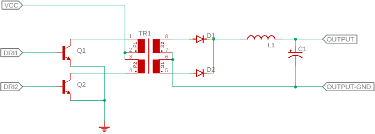
Two NPN transistors will enable push-pull functionality. The two transistors Q1 and Q2 cannot be turned on at the same time. When the Q1 is turned on, the Q2 will remain turned off, when the Q1 is turned off, the Q2 will turn on. It will happen sequentially and will continue as a loop.
As we can see, the above circuit uses a transformer, this is an isolated push-pull converter.
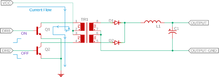
The above image is showing the state where the Q1 is turned on and the Q2 will turn off. Thus the current will flow through the center tap of the transformer and will go to the ground via the transistor Q1 while the Q2 will block the current flow on the other tap of the transformer. Exactly the opposite thing happens when the Q2 turns on and Q1 remains turned off. Whenever the changes in the current flow occur, the transformer transfers the energy from the primary side to the secondary side.
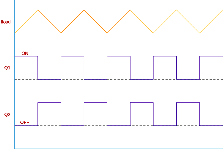
The above graph is very useful to check how this happens, at first, there used to be no voltages or current flow in the circuit. Q1 turned on, a constant voltage first strike to the tap as the circuit is closed now. The current starts to increase and then the voltage is induced into the secondary side.
In the next phase, after a time delay, the transistor Q1 turns off and Q2 is turned on. Here comes a few important things at work - transformer parasitic capacitance and the inductance forms an LC circuit that starts switching in opposite polarity. The charge starts to flow back in the opposite direction through the other tap winding of the transformer. In this fashion, the current is constantly pushed in alternate modes by those two transistors. However, as the pulling is done by the LC circuit and the center tap of the transformer, it is called push-pull topology. Often it is described in such a way that the two transistors push the current alternately naming the convention push-pull where transistors do not pull the current. The load waveform looks like the sawtooth, however, it is not that is shown in the above waveform.
As we have learned how a push-pull converter design works, let's move on to building an actual circuit for it, and then we can analyze that on the bench. But before that, let's take a look at the schematic.
Components required to build a Practical Push Pull Converter
Well, the below circuit is constructed on a breadboard. The components used for testing circuits are as follows-
- 2 Pcs inductors having the same rating - 220uH 5A toroidal inductor.
- 0.1uF polyester film capacitor - 2 pcs
- 1k resistor 1% - 2 pcs
- ULN2003 Darlington pair transistor
- 100uF 50V capacitor
A Practical Push-Pull Converter Circuit Diagram
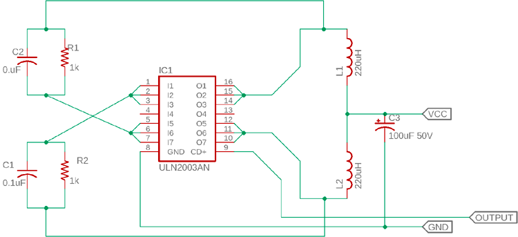
The schematic is pretty straight forward. Let's analyze the connection, the ULN2003 is the Darlington pair transistor array. This Transistor array is useful as the freewheeling diodes are available inside the chipset and it does not require any additional components thus avoiding any additional complex routing on a breadboard. For the synchronous driver, we are using a simple RC timer that will synchronously turn on and off the transistors to create a push-pull effect across the Inductors.
Practical Push-Pull Converter - Working
The working of the circuit is simple. Let’s remove the Darlington pair and make the circuit simple using two transistors Q1 and Q2.
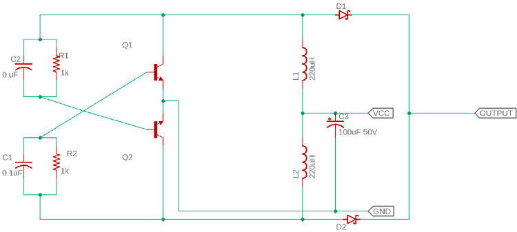
The RC networks are connected in a cross position with the base of Q1 and Q2, which turn on the alternate transistors using a feedback technique called regenerative feedback.
It starts operating like this - When we apply voltage to the center tap of the transformer (where the common connection between two inductors), the current will flow through the transformer. Depending on the flux density and saturation of the polarity, negative or positive, the current first charges up C1 and R1 or C2 and R2, not both. Let's imagine C1 and R1 get the current first. The C1 and R1 provide a timer which turns on the transistor Q2. The L2 section of the transformer will induce voltage using the magnetic flux. In this situation, the C2 and R2 start to charge up and turn on the Q1. The L1 section of the transformer then induces a voltage. The timing or the frequency is entirely dependent on the input voltage, the saturated flux of the transformer or inductor, the primary turns, cross-sectional square centimeter area of the core. The formula of the frequency is-
f = (Vin * 108) / (4 * βs * A * N)
Where Vin is the input voltage, 108 is a constant value, βs is the saturated flux density of the core that will be reflected on the transformer, A is the cross-sectional area and N is the number of turns.
Testing the Push Pull Converter Circuit
For testing the circuit, the following tools are required-
- Two millimeters - one for checking input voltage and another one for output voltage
- An Oscilloscope
- A bench power supply.
The circuit is constructed in a breadboard and the power is slowly increased. The input voltage is 2.16V whereas the output voltage is 8.12V, which is almost four times the input voltage.
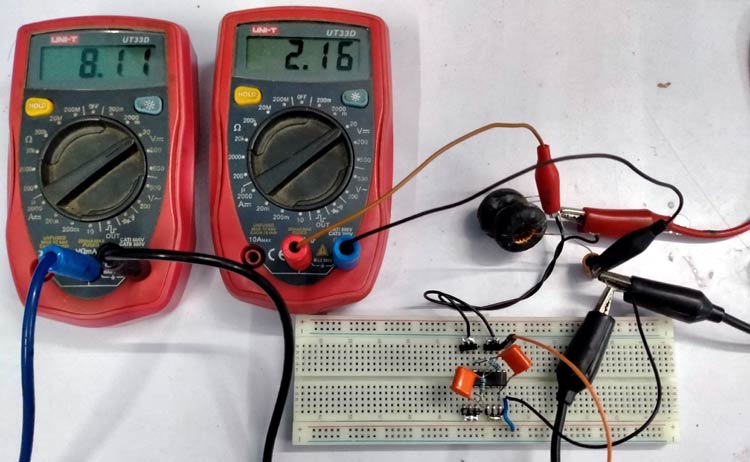
However, this circuit does not use any feedback topology, so the output voltage is not constant and nor isolated.
The frequency and the switching of the push-pull is observed in the oscilloscope-
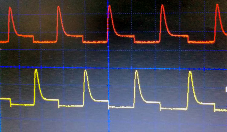
Thus the circuit is now acting as a push-pull boost converter where the output voltage is not constant. It is expected that this push-pull converter could provide wattage up to 2W, but we have not tested it due to the lack of feedback generation.
Conclusions
This circuit is a simple form of the push-pull converter. However, it is always recommended to use a proper push-pull driver IC for the desired output. The circuit can be constructed in a manner where isolated or non-isolated, any topologies in push-pull conversion can be built.
The below circuit is a proper circuit of controlled push-pull DC to DC converter. It is a 1:1 push-pull converter using LT3999 for Analog Devices (Linear Technologies).
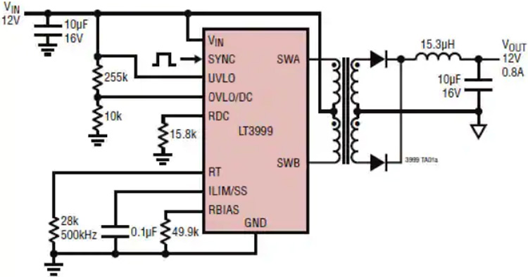
I hope you liked the article and learned something new if you have any questions regarding this topic, do put a comment down below, or you can post your question directly on our forum.


