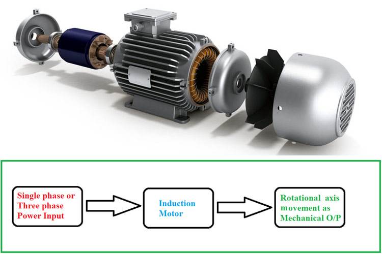
The induction motor is an A.C electrical machine that converts electrical energy into mechanical energy. Induction motor is used extensively in variously applications from basic domestic appliances to heavy industries. The machine has so many applications that are hard to count and you can imagine the scale by knowing that almost 30% of electrical power generated globally gets consumed by induction motors itself. This amazing machine is invented by the great scientist Nikola Tesla and this invention has permanently altered the course of human civilization.
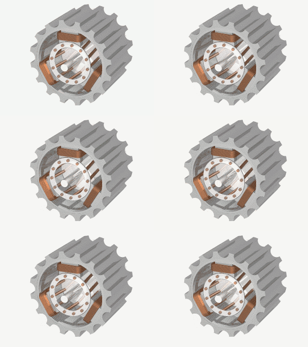
Here are few applications of a single-phase and three-phase induction motors that we can find in daily life.
Applications of Single Phase Induction motors:
- Electric fans in the home
- Drilling machines
- Pumps
- Grinders
- Toys
- Vacuum cleaner
- Exhaust fans
- Compressors and electric shavers
Applications of Three Phase Induction motors:
- Small scale, Medium-scale and large scale industries.
- Lifts
- Cranes
- Driving lathe machines
- Oil extracting mills
- Robotic arms
- Conveyers belt system
- Heavy crushers
The induction motors come in many sizes & shapes having relative features and electrical ratings. They vary from few centimeters to a few meters in size and have a power rating from 0.5Hp to 10000Hp. The user can choose the most appropriate one from the ocean of models to meet his/her demand.
We have already discussed the Fundamentals of Motors and its working in the previous article. Here we will discuss the Induction Motor’s construction and working in detail.
Working Principle of Induction Motor
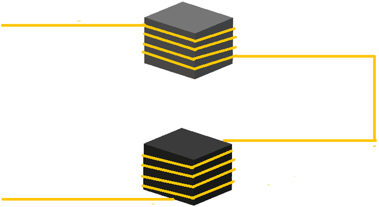
For understanding the working principle of an induction motor, let us consider a simple setup first as shown in the figure.
Here,
- Two iron or ferrite cores of equal sizes are taken and are suspended in the air at a distance.
- An enameled copper wire is wounded on the top core followed by the bottom one and two ends are taken to one side as shown in the figure.
- The core here acts as a medium for carrying and concentrating the magnetic flux generated by the coil during operation.
Now, if we connect an alternating voltage source at the two ends of the copper, we will have something like below.
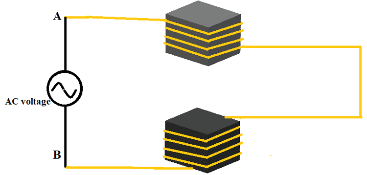
During the positive cycle of AC:
Here during the first half cycle, the positive voltage at point ‘A’ will gradually goes from zero to maximum and then comes back to zero. During this period the current flow in the winding can be represented as.
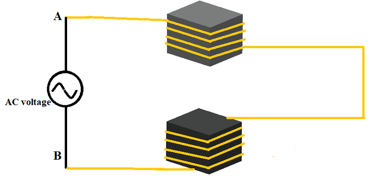
Here,
- During the positive cycle of the AC power source, the current in both the windings increases gradually from zero to maximum and then gradually goes back from maximum to zero. This is because according to Ohms law, the current in a conductor is directly proportional to terminal voltage, and we discussed it many times in previous articles.
- The windings are wound in a way that current in both windings flow in the same direction, and we can see the same represented in the diagram.
Now let us remember a law called Lenz’s law we studied earlier before going forward. According to Lenz’s law, ‘A conductor carrying a current will generate a magnetic filled around its surface‘,
and if we apply this law in the above example, then a magnetic field will be generated by each loop in both the coils. If we add magnetic flux generated by the entire coil, then it will get a considerable value. This entire flux will appear on the iron core as the coil was wound on the core body.
For convenience, if we draw the magnetic flux lines concentrated on the iron core on both ends, then we will have something like below.
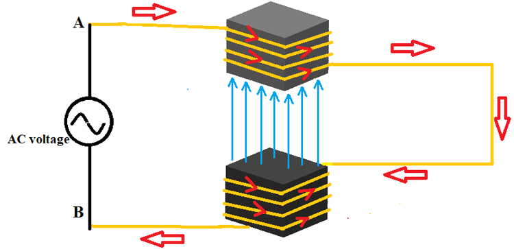
Here you can see the magnetic lines getting concentrated on the iron cores and its movement through the air gap.
This flux intensity is directly proportional to the current flowing in coils wound on both the iron bodies. So during the positive half cycle, the flux goes from Zero to Maximum and then toned down from Maximum to Zero. Once the positive cycle completed the field intensity at the air gap also reaches zero and after this, we will have a negative cycle.
During the negative cycle of AC:
During this negative cycle of the sinusoidal voltage, the positive voltage at point ‘B’ will gradually goes from zero to maximum and then comes back to zero. As usual, because of this voltage, there will a current flow and we can see the direction of this current flow in the windings in the figure below.
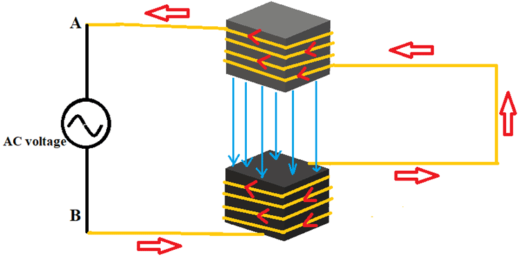
Since the current is linearly proportional to voltage, its magnitude in both the windings increases gradually from zero to maximum and then goes down from maximum to zero.
If we consider Lenz’s law, then a magnetic field will appear around the coils because of the current flow similar to the case studied in the positive cycle. This field will get concentrated at the center of ferrite cores as shown in the figure. Since the flux intensity is directly proportional to the current flowing in coils wound on both the iron bodies, this flux will also goes from Zero to Maximum and then toned down from Maximum to Zero following the magnitude of the current. Although this is similar to a positive cycle, there is a difference and that is the direction of the magnetic field lines. You can observe this difference in flux direction on diagrams.
After his negative cycle comes a positive cycle followed by another negative cycle and it goes on like that until the AC sinusoidal voltage is removed. And because of this interchanging voltage cycle, the magnetic field at the center on iron cores keeps changing in both magnitude and direction.
In conclusion by using this setup,
- We have developed a magnetic field concentrated area at the center of the iron cores.
- The magnetic field intensity at the air gap keeps changing in both magnitude and direction.
- The field follows the AC sinusoidal voltage waveform.
Faradays Law of Electromagnetic Induction
This setup we have discussed until now is best suited to realize the Faradays law of electromagnetic induction. This is because a constantly changing magnetic field is the most basic and important requirement for electromagnetic induction.
We are studying this law here because Induction motor works on the principle of Faraday's law of electromagnetic induction.
Now to study the phenomenon of electromagnetic induction, let us consider the setup below.
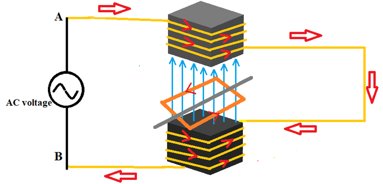
- A conductor is taken and shaped it into a square with both ends short-circuited.
- A metal rod is fixated at the center of the conductor square which acts as the axis of the setup.
- Now conductor square can rotate freely along the axis and is called a rotor.
- The rotor is placed at the center of the air gap so that the conductor loop can experience the maximum field generated by rotor coils.
We know according to Faraday's law of electromagnetic induction, ‘when a varying magnetic field cuts a metal conductor, then an EMF or voltage gets induced in the conductor’.
Now, let us apply this law to understand the working of an Induction motor:
- According to this law of electromagnetic induction, an EMF should get induced in the rotor conductor placed at the center because of the changing magnetic field experienced by it.
- Because of this induced EMF and conductor being short-circuited a current get flowed in the entire loop as shown in the figure.
- Here comes the key to working of Induction motor, We know according to Lenz’s law a current-carrying conductor generates a magnetic field around it whose intensity is proportional to the magnitude of the current.
- Since the law is universal then the conductor loop of the rotor must also generate a magnetic field because the current is flowing through it because of electromagnetic induction.
- If we call the magnetic field generated by stator windings and iron core setup as Main flux or Stator flux. Then we can call the magnetic field generated by the conductor loop of the rotor as Rotor flux.
- Because of the interaction between Main flux and the Rotor flux a force gets experienced by the rotor. This force tries to oppose the EMF induction into the rotor by adjusting the position of the rotor. Hence we will experience a movement in the shaft position at this time.
- Now the magnetic field keeps changing because of alternating voltage the force also keeps adjusting the rotor position continuously without stop.
- So the rotor keeps rotating because of alternating voltage and thereby we have mechanical output at the shaft or the axis of the rotor.
With that, we have seen how because of Electromagnetic induction into the rotor we have mechanical output at the shaft. So the name given for this setup is called Induction Motor.
Up until now what we have discussed is the working principle of induction motor but do remember that both theory and practical are different. And for working of induction motor an additional setup is needed which we will discuss below.
Single Phase Induction Motor
The Induction motor which works on single-phase AC power is called Single Phase Induction Motor.
The power line available for us at homes is 240V/50Hz AC single-phase power line and the Inductions motors which we use in our day to day life in our homes are called Single Phase Induction Motors.
For better understanding the working principle of single phase induction motor, let us look into the construction of Single Phase Induction Motor.
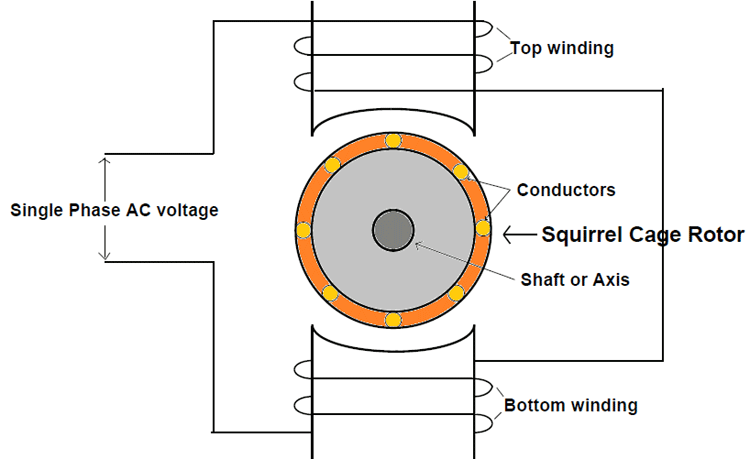
Here,
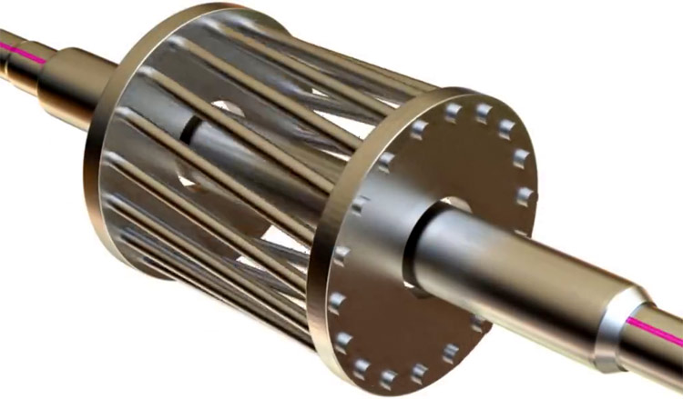
- We will take multiple conductors and mounted them on the freely rotating shaft as shown in the figure.
- Also, we will short the ends of all conductors with a metal ring thereby creating multiple conductors loops which we have studied earlier.
- This rotor setup looks like a squirrel cage at a closer look and hence it is called a squirrel cage Induction Motor. Here let’s have a look at the 3D structure of squirrel cage rotor.
- The stator which was considered to be a complete iron piece is actually a group of thin iron sheets stacked together. They are so closely pressed together there will literally no air between them. We use a stack of iron sheets instead of a single iron piece for the same reason we use rolled iron sheets in the case of a power transformer that is to reduce iron losses. By using the stacking method we will reduce power loss considerably while keeping by performance the same.
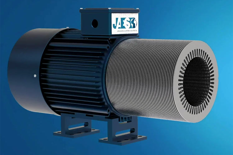
The working of this setup is similar to the setup used in explaining the working principle of the induction motor.
- First, we will provide the AC voltage and because of this voltage, current flows through stator winding wound on both top and bottom segments.
- Because of the current, a magnetic field gets generated on both top and bottom windings.
- The bulk of iron sheets acts as a core medium for carrying the magnetic field generated by the coils.
- This alternating magnetic field carried by the iron core gets concentrated at the central air gap because of the intentional structural design.
- Now since the rotor is placed in this air gap the shorted conductors fixated on the rotor also experience this alternating field.
- Because of the field, a current gets induced in the conductors of the rotor.
- Since the current is passing through the rotor conductors a magnetic field will also get generated around the rotor.
- Upon the interaction between the generated rotor magnetic field and stator magnetic field, a force gets experienced by the rotor.
- This force moves the rotor along the axis and thereby we will have rotational motion.
- Since the voltage is continuously changing sinusoidal voltage the rotor also keeps rotating continuously along its axis. Thereby we will have a continuous mechanical output for given single phase input voltage.
Although we have assumed the rotor will rotate automatically after the power is given to the single-phase motor that is not the case. Since the field generated by a single-phase induction motor is an alternating magnetic field and not a rotating magnetic field. So at the start of the motor, the rotor gets locked on its position because the force experienced by it because of the bottom coil and the top coil will be of the same magnitude and opposite in direction. So at the start, the net force experienced by the rotor is zero. To avoid this we will use auxiliary winding for the induction motor to make it a self-starting motor. This auxiliary winding will provide the necessary field to make the rotor move at the start. The example for this case is the electric fan we see in our daily life, which is a capacitor start and runs an induction motor with auxiliary winding connected in series with the capacitor.
Three Phase Induction Motor
The Induction motor which works on three-phase AC electric power is called Three Phase Induction Motor. Usually, Three Phase Induction Motors are used in industries and are not suitable for home applications.
The power line available for industries is 400V/50Hz Three phase four line AC power and the Inductions motors which work on this supply in industries are called Three Phase Induction Motors.
For better understanding the working principle of three-phase induction motor let us look into the construction of Three Phase Induction Motor.
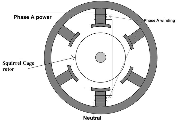
Here,
- Phase A winding starts from the top segment followed by the bottom segment as shown in the figure.
- As for the two ends of Phase, A winding one is connected to Phase A power line of three-phase power supply while the other end is connected to the neutral of the same three phases four-line power supply. This is possible because in a three-phase four-line power supply we have first three lines carrying three line voltages while the fourth line is neutral.
- The other two-phase windings follow the same pattern as Phase A. In the two ends of Phase B winding one is connected to the Phase B power line of three-phase power supply while the other end is connected to the neutral of same three phases four-line power supply.
- The structure of the rotor is similar to a squirrel cage and is the same type of rotor which is used in a single-phase induction motor.
Now if we provide the electric power to the three-phase windings of the stator then the current starts flowing in all three windings. Because of this current flow, a magnetic field will be generated by the coils and this field will flow through less magnetic resistivity path provided by the laminated core. Here the structure of the motor is so designed that the magnetic field carried by core gets concentrated on the air gap at the center where the rotor is placed. So the magnetic field concentrated by core at the center gap influences the conductors in the rotor thereby inducing a current in them.
In the presence of conductor current, the rotor also generates a magnetic field that interacts with the stator field at any given time. And due to this interaction the rotor experience a force which lead to rotation of the motor.
Here the magnetic field generated by the stator is of rotating type because of three-phase power, unlike the alternating type we discussed in a single-phase motor. And because of this rotating magnetic field, the rotor starts rotating by itself even in the absence of an initial push. This makes the Three Phase motor a self-starting type and we do not need any auxiliary winding for this type of motor.


