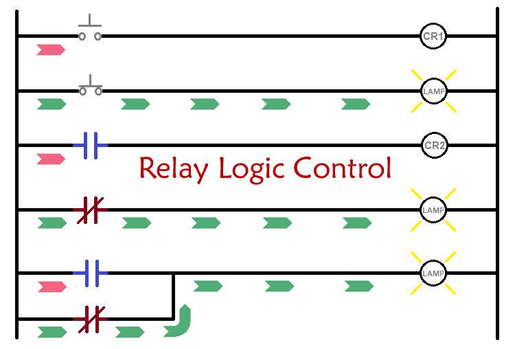
Relay logic basically consists of relays wired up in a particular fashion to perform the desired switching operations. The circuit incorporates relays along with other components such as switches, motors, timers, actuators, contactors etc. The relay logic control works efficiently to perform basic ON/OFF operations by opening or closing the relay contacts but it involves a humongous wiring. Here we will learn about Relay Logic Control Circuit, its symbols, working and how they can be used as Digital Logic Gates.
Working of a Relay
Relay act as switch which is operated by a small amount of current. The relay has two contacts-
- Normally open (NO)
- Normally Close (NC)
In the figure given below, you can see there are two sides of a Relay. One is primary coil which acts as a electromagnet on passing current through it and other one is secondary side having NO and NC contacts.
When the contact position is Normally Open, the switch is Open and hence the circuit is Open and no current flows through the circuit. When the contact position is Normally Close, the switch is closed and the circuit is completed and hence current flows through the circuit.
This change of state in the contacts occur whenever a small electrical signal is applied i.e. whenever a small amount of current flows through the relay, the contact changes.
This is explained through the figures below-
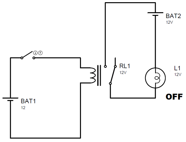
Above figure shows the switch in NO contact position. In this figure, primary circuit (coil) is not completed and hence no current flows through the electromagnetic coil in that circuit. Therefore, the connected bulb remains off as the relay contact remains open.
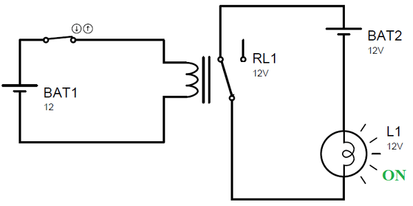
Now the above figure shows the switch in NC contact position. In this figure, primary circuit (coil) is closed, so there is some current through the coil connected in that circuit. Due to the current flowing in this electromagnetic coil, a magnetic field is created in its vicinity and due this magnetic field, the relay is energised and hence closes its contacts. Therefore, the connected bulb turns ON.
You can find the detailed article on Relay here and learn how relay can be used any circuit.
Relay Logic Circuits - Schematic/Symbols
A relay logic circuit is a schematic diagram which shows various components, their connections, inputs as well as outputs in a particular fashion. In relay logic circuits, the contacts NO and NC are used to indicate Normally Open or Normally Close relay circuit. It contains two vertical lines, one on the extreme left and the other on the extreme right. These vertical lines are called rails. The extreme left rail is at the supply voltage potential and is used as an input rail. The extreme right rail is at zero potential and is used as the output rail.
Particular symbols are used in relay logic circuits to represent different circuit components. Some of the most common and widely used symbols are given below-
1. NO contact

The given symbol indicates a Normally Open contact. If the contact is Normally open, it would not allow any current to pass through it and hence there will be an Open circuit at this contact.
2. NC contact

This symbol is used to indicate Normally Close contact. This allows the current to pass through it and acts as a short circuit.
3. Push Button (ON)

This push button allows current to flow through it to the rest of the circuit as long as it is pressed. If we release the push button, it becomes OFF and no longer allows the current to flow. This means in order to carry the current the push button has to remain in the pressed state.
4. Push Button (OFF)

The OFF push button indicates an open circuit i.e. it does not allow the flow of current through it. If the push button is not pressed, it stays in OFF state. It can transit into ON state to carry the current through it once it is pressed.
5. Relay coil

The relay coil symbol is used to indicate control relay or motor starter and sometimes even contactor or timer.
6. Pilot Lamp
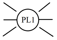
The given symbol denotes Pilot Lamp or simply a bulb. They indicate the machine operation.
Relay Logic Circuit – Examples and Working
The working of a relay logic circuit can be explained through the given figures-
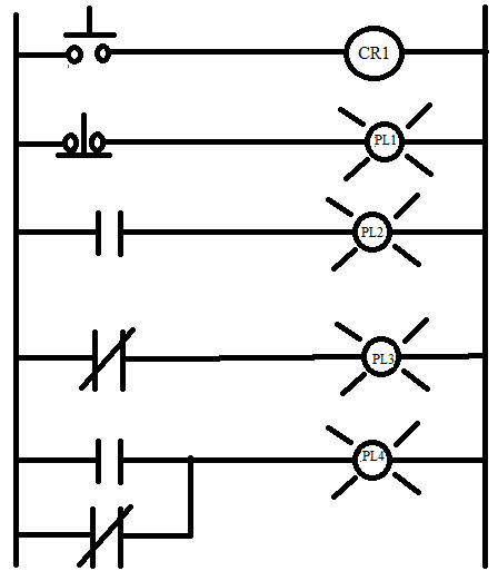
This figure shows a basic relay logic circuit. In this circuit,
Rung 1 contains one Push button (initially OFF) and one control relay.
Rung 2 contains one Push button (initially ON) and one Pilot lamp.
Rung 3 contains one NO contact and one Pilot lamp.
Rung 4 contains one NC contact and one pilot lamp.
Rung 5 contains one NO contact, one pilot lamp and a sub-rung with one NC contact.
To understand the working of the given relay logic circuit, consider below figure
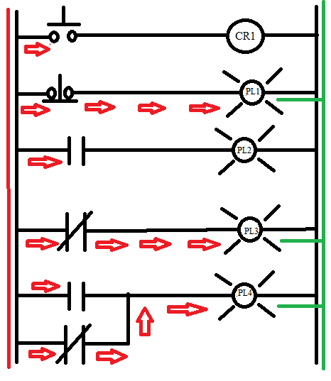
In rung 1, the push button is Off and hence it does not allow the current to pass through it. Therefore, there is no output through rung 1.
In rung 2, the push button is On and therefore, current passes from the high voltage rail to the low voltage rail and the Pilot Lamp 1 glows.
In rung 3, the contact is Normally Open, therefore Pilot lamp 2 remains Off and there is no flow of current or output through the rung.
In rung 4, the contact is normally Close, thereby allowing the current to pass through it and giving an output to the low voltage rung.
In rung 5, no current flows through the main rung as the contact is normally Open but due to the presence of the sub-rung, which contains a normally close contact, there is a flow of current and hence the pilot lamp 4 glows.
Basic Logic Gates Using Relay Logic
Basic digital logic gates can also be realised using relay logic and have a simple construction using the contacts as given below-
1. OR Gate – Truth table for OR gate is as shown –
|
A |
B |
O/P |
|
0 |
0 |
0 |
|
0 |
1 |
1 |
|
1 |
0 |
1 |
|
1 |
1 |
1 |
This table is realised using the relay logic circuit in the following manner –
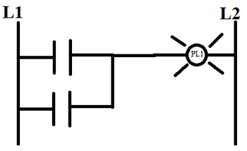
In this, the Pilot lamp will turn On whenever any one of the inputs becomes one which makes the contact associated with that input as normally close. Otherwise, the contact remains Normally open.
2. AND Gate – Truth table for AND gate is given as –
|
A |
B |
O/P |
|
0 |
0 |
0 |
|
0 |
1 |
0 |
|
1 |
0 |
0 |
|
1 |
1 |
1 |
Relay logic realisation of AND gate is given by –
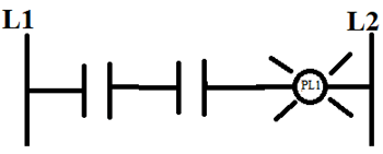
The contacts are connected in series for AND gate. This means that the pilot lamp will turn ON if and only if both the contacts are Normally close i.e. when both the inputs are 1.
3. NOT Gate – Truth table for NOT gate is given by –
|
A |
O/P |
|
0 |
1 |
|
1 |
0 |
The equivalent relay logic circuit for the given NOT gate truth table is as follows –
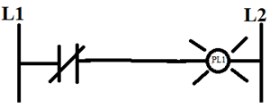
The pilot lamp lights up when the input is 0 so that the contact remains normally close. As the input changes to 1, the contact changes to normally Open and hence the pilot lamp doesn’t light up giving the output as 0.
4. NAND Gate – The NAND gate truth table is as follows –
|
A |
B |
O/P |
|
0 |
0 |
1 |
|
0 |
1 |
1 |
|
1 |
0 |
1 |
|
1 |
1 |
0 |
The relay logic circuit as realised for the given truth table is as –
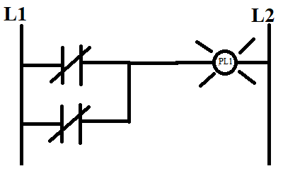
As two Normally close contacts are connected in parallel, the pilot lamp lights up when one or both the inputs are 0. However, if both the inputs become 1, both the contacts become Normally Open and hence the output becomes 0 i.e. the pilot lamp doesn’t light up.
5. NOR Gate – The truth table for NOR gate is given by the following table –
|
A |
B |
O/P |
|
0 |
0 |
1 |
|
0 |
1 |
0 |
|
1 |
0 |
0 |
|
1 |
1 |
0 |
The given truth table can be implemented using the relay logic as follows –
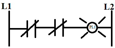
Here, two normally close contacts are connected in series which means the pilot lamp will light up only if both the inputs are 0. If any one of the input becomes 1, that contact changes to normally open and hence the flow of current is interrupted, thereby causing the pilot lamp not to light up, indicating 0 output.
Disadvantages of RLC over PLC
- Complex wiring
- More time to implement
- Comparatively less accuracy
- Difficult to maintain
- Fault detection is hard
- Provide less flexibility


