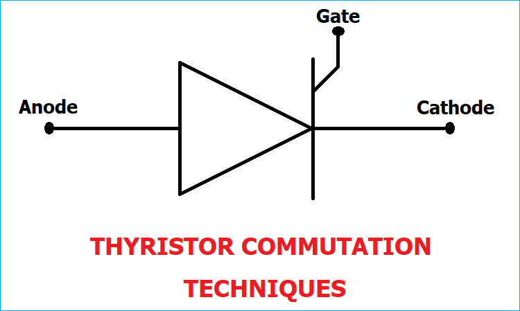
To turn On a Thyristor, there are various triggering methods in which a trigger pulse is applied at its Gate terminal. Similarly, there are various techniques to turn Off a Thyristor, these techniques are called Thyristor Commutation Techniques. It can be done by bringing the Thyristor back into the forward blocking state from the forward conduction state. To bring the Thyristor into forward blocking state, forward current is reduced below the holding current level. For the purpose of power conditioning and power control a conducting Thyristor must be commutated properly.
In this tutorial, we will explain the various Thyristor Commutation Technique. We already explained about Thyristor and its Triggering Methods in our previous Article.
There are mainly two techniques for Thyristor Commutation: Natural and Forced. The Forced commutation technique is further divided into five categories which are Class A, B, C, D, and E.
Below is the Classification:
- Natural Commutation
- Forced Commutation
- Class A: Self or Load Commutation
- Class B: Resonant-Pulse Commutation
- Class C: Complementary Commutation
- Class D: Impulse Commutation
- Class E: External Pulse Commutation
Natural Commutation
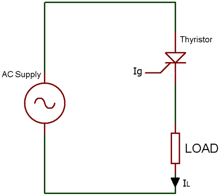
Natural Commutation occurs only in AC circuits, and it is named so because it doesn’t require any external circuit. When a positive cycle reaches to zero and the anode current is zero, immediately a reverse voltage (negative cycle) is applied across the Thyristor which causes the Thyristor to turn OFF.
A Natural Commutation occurs in AC Voltage Controllers, Cycloconverters, and Phase Controlled Rectifiers.
Forced Commutation
As we know there is no natural zero current in DC Circuits like as natural commutation. So, Forced Commutation is used in DC circuits and it is also called as DC commutation. It requires commutating elements like inductance and capacitance to forcefully reduce the anode current of the Thyristor below the holding current value, that’s why it is called as Forced Commutation. Mainly forced commutation is used in Chopper and Inverters circuits. Forced commutation is divided into six categories, which are explained below:
1. Class A: Self or Load Commutation
Class A is also called as “Self-Commutation” and it is one of the most used technique among all Thyristor commutation technique. In the below circuit, the inductor, capacitor and resistor form a second order under damp circuit.
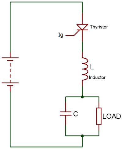
When we start supplying the input voltage to the circuit the Thyristor will not turn ON, as it requires a gate pulse to turn ON. Now when the Thyristor turns ON or forward biased, the current will flow through the inductor and charges the capacitor to its peak value or equal to the input voltage. Now, as the capacitor gets fully charged, inductor polarity gets reversed and inductor starts opposing the flow of current. Due to this, the output current starts to decrease and reach to zero. At this moment the current is below the holding current of the Thyristor, so the Thyristor turns OFF.
2. Class B: Resonant-Pulse Commutation
Class B commutation is also called as Resonant-Pulse Commutation. There is only a small change between Class B and Class A circuit. In class B LC resonant circuit is connected in parallel while in Class A it’s in series.
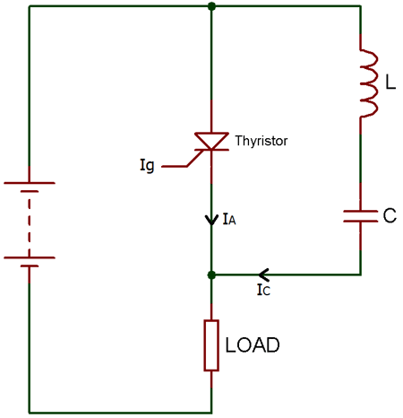
Now, as we apply the input voltage, the capacitor starts charging upto the input voltage (Vs) and Thyristor remains reversed biased until the gate pulse is applied. When we apply the gate pulse, the Thyristor turns ON and now the current start flowing from both the ways. But, then the constant load current flows through the resistance and inductance connected in series, due to its large reactance.
Then a sinusoidal current flow through the LC resonant circuit to charge the capacitor with the reverse polarity. Hence, a reverse voltage appears across the Thyristor, which causes the current Ic (commutating current) to oppose the flow of the anode current IA. Therefore, due to this opposing commutating current, when the anode current is getting lesser than the holding current, Thyristor turns OFF.
3. Class C: Complementary Commutation
Class C commutation is also called as Complementary Commutation. As you can see the circuit below, there are two Thyristor in parallel, one is main and another is auxiliary.
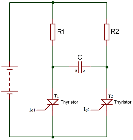
Initially, both the Thyristor are in OFF condition and the voltage across capacitor is also zero. Now, as the gate pulse is applied to the main Thyristor, the current will start flowing from two paths, one is from R1-T1 and second is R2-C-T1. Hence, the capacitor also starts charging to the peak value equal to the input voltage with the polarity of plate B positive and plate A negative.
Now, as the gate pulse is applied to the Thyristor T2, it turns ON and a negative polarity of current appear across the Thyristor T1 which cause T1 to get turn OFF. And, the capacitor starts charging with the reverse polarity. Simply we can say that when T1 turns ON it turns OFF T2 and as T2 turns ON it turns OFF T1.
4. Class D: Impulse Commutation
Class D commutation is also called as Impulse Commutation or Voltage Commutation. As Class C, Class D commutation circuit also consists of two Thyristor T1 and T2 and they are named as main and auxiliary respectively. Here, diode, inductor, and auxiliary Thyristor form the commutation circuit.
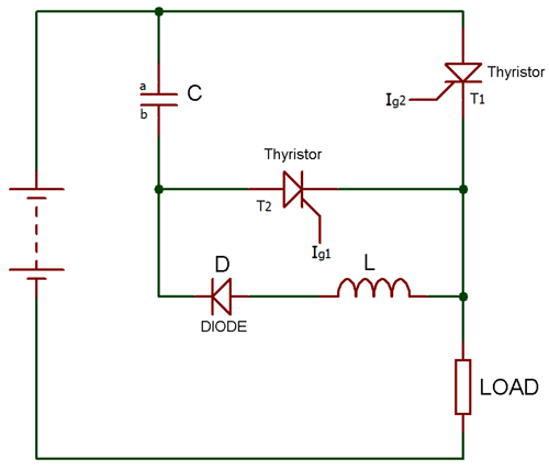
Initially, both the Thyristor are in OFF state and voltage across capacitor C is also zero. Now as we apply the input voltage and trigger the Thyristor T1 the load current starts flowing through it. And, the capacitor starts charging with polarity of plate A negative and plate B positive.
Now, as we trigger the auxiliary Thyristor T2, the main Thyristor T1 turns OFF and the capacitor starts charging with the opposite polarity. When it gets full-charged, it causes the auxiliary Thyristor T2 to turn OFF, because a capacitor does not allow the flow of current through it when it gets fully charged.
Therefore, the output current will also be zero because at this stage because of both the Thyristors are in OFF state.
5. Class E: External Pulse Commutation
Class E commutation is also called External Pulse Commutation. Now, you can see in the circuit diagram, the Thyristor is already in forward bias. So, as we trigger the Thyristor, the current will appear at the load.
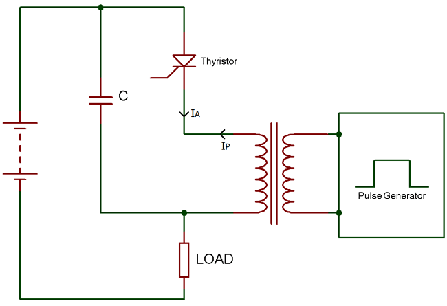
The capacitor in the circuit is used for the dv/dt protection of the Thyristor and the pulse transformer is used to turn OFF the Thyristor.
Now, when we give pulse through the pulse transformer an opposite current will flow in the direction of the cathode. This opposite current oppose the flow of the anode current and if IA – IP < IH Thyristor will turn OFF.
Where IA is Anode current, IP is pulse current and IH is holding current.


