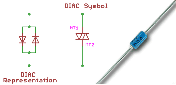
DIAC is a semiconductor device which has three layers and two junctions. The word DIAC consists of two parts, DI and AC. The DI stands for the diode (or two. Like Di, Tri, Quad, Penta etc.) and AC stands for Alternating Current. DIAC is the acronym of the diode for alternating current.
In the below image the DIAC symbol is shown.
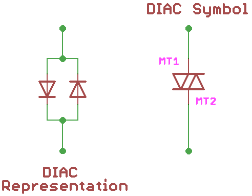
The DIAC is a combination of two diodes in parallel, one in forward bias and the other one is in reverse bias condition with respect to both sides. DIAC is a specially constructed diode, which allows current to pass in both directions when certain conditions are met.
One more interesting thing about the DIAC is, due to no specified direction of current flow, it is considered as a bidirectional device. DIAC only has two Anode pins, and no cathode pins are there. Those two anode terminals are often referred to Main Terminal 1 (MT1) and Main Terminal 2 (MT2).
Construction of DIAC
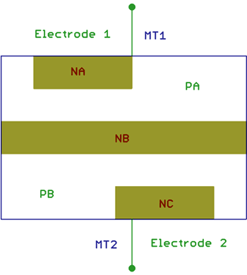
DIAC construction follows the same rule as a typical transistor construction without the Base terminal. As discussed above, the DIAC construction has two main terminals, MT1, and MT2. The DIAC construction uses two P-type materials and three N-type materials without the gate terminal.
In the above image, Three N-type regions are shown with the name of NA, NB, and NC.
P-type regions are shown as PA and PB. If MT1 terminal became more positive than MT2, the current will flow in the direction of PA -> NB -> PB -> NC. When the reverse situation occurs, the MT2 terminal became more positive than the MT1 and the current will flow in a direction of PB -> NB -> PA -> NA.
The DIAC only starts to conduct the current when the breakdown voltage is reached.
During the breakdown situations, there is a sudden decrease in the voltage drop occurs across the DIAC and the current flow will increase through it. This state is called a negative dynamic resistance region. The conduction continues until the current decreases to a a certain value called as holding current. Below this holding current, the DIAC resistance becomes high and it will enter in non-conducting state.
As DIAC is a bidirectional device, it will happen for both directions of the current.
DIAC Characteristic Curve
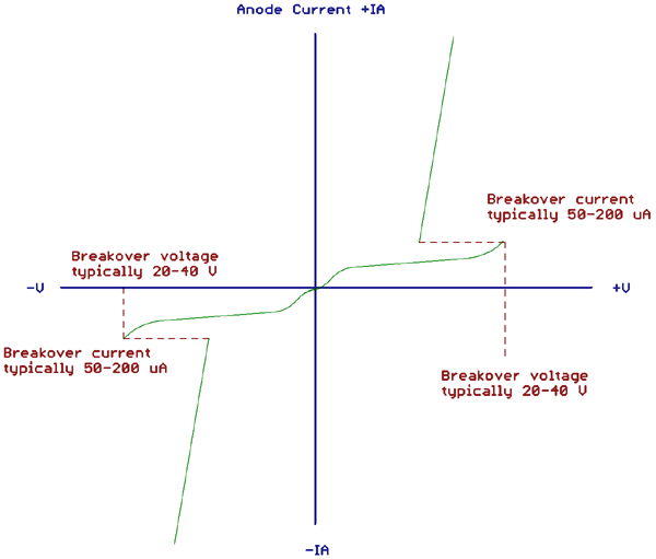
In the above image, the actual I-V characteristic of DIAC is shown. The curve looks like the English word Z. The DIAC remains in the nonconductive state until the breakdown voltage is reached. The slow curve before going to the straight line is due to the leakage current. After the breakdown voltage is reached, the DIAC enters into the low resistance state and the current flow through the diode is rapidly increased which is shown as a straight line. But during the current conducting state the voltage drop across the diode is reduced, hence the line is not perfect 90 degrees.
DIAC Applications
The DIAC is designed specifically to trigger TRIAC or an SCR. As discussed above, the DIAC goes into avalanche conduction at the breakover voltage. Due to this, the device exhibits negative resistance characteristics and the voltage drop across it dramatically decreases, typically to about 5 Volts. This creates a break over current which is sufficient to turn on or trigger a TRIAC or an SCR.
The DIAC is also applicable for symmetrical triggering applications, as the DIAC conducts in both directions.
Now the most important question is, why we need DIAC to trigger a TRIAC?
TRIAC do not fire symmetrically and because of this, TRIAC do not trigger at the same gate voltage level for one polarity as for the other one. This leads to an undesirable result. The unsymmetrical firing results in a current waveform which has a greater variety of harmonic frequencies leads to uncertain possibilities inside the Power circuit. To recover from this situation and to reduce the harmonic contents in a power system, DIAC is placed in series with the gate of a TRIAC.
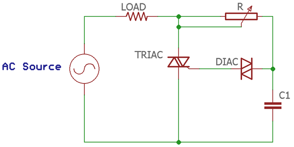
Basic DIAC application is shown in the below image where the DIAC is being used as a triggering device of the TRIAC.
The DIAC is connected in series with the gate of a TRIAC. The DIAC do not allow any gate current until the triggering voltage has reached to a certain repeatable level in both directions. In this case, the firing point of the TRIAC from one-half cycle to the next half cycle tends to be more consistent and it reduces the total harmonic content of the system.
Practical Example of DIAC
Let's see a practical circuit using DIAC. In the below circuit a DIAC is used to blink a LED.
The construction is fairly simple, it consists two 1N4007 diode which is a 1000V 1A rectifier diode and a 47uF capacitor with at least 300V rating. For the DIAC, DB3, DB4 or NTE6408 can be used. Two resistors of 20k and 100 Ohms (½ Watt) are used along with a blue color standard LED, (3v)

Here two diodes are used for safety purpose which convert AC into DC. Capacitor quickly gets charged by the diodes, and as soon as the charged voltage reaches DIAC‘s breakdown voltage, it starts to conduct and turn on the LED. After turning on the LED and while the current is passing through the DIAC, the voltage drop decreases and the capacitor star discharging through the resistor 20k.
Turn on and off time of the LED can be controlled by changing the capacitor value.
In the below, the simulation is shown in Proteus.
The Quadrac construction
Quadrac is a special type of Thyristor which uses DIAC and TRIAC in a single package. In this device, DIAC is used to internally trigger the TRIAC. Quadrac has a wide range of applications like switching, temperature modulation control, Speed control or various dimmer related applications.


