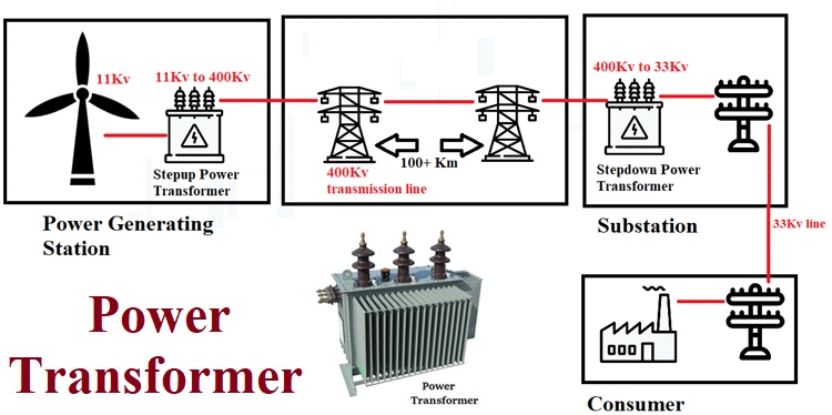
In some of our previous articles we have discussed about the basics of the transformer and its different types. One of the important and commonly used Transformer is Power transformer. It is very widely used for stepping up and stepping down the voltage at the electrical power generating station and distribution station (or substation) respectively.
For example, consider the block diagram shown above. Here power transformer is used two times while delivering electric power to a consumer who is far away from the generating station.
- First time is at power generating station to step-up the voltage generated by the wind generator.
- Second is at the distribution station (or substation) to step-down the voltage received at the end of the transmission line.
Power Loss in Transmission Lines
There are many reasons for using a power transformer in electrical power systems. But one of the most important and simple reason for using the power transformer is to reduce power losses during electric power transmission.
Now let’s see how power loses is reduced considerably by using a power transformer:
First, the equation of Power loss P = I*I*R.
Here I = current through the conductor and R = Resistance of conductor.
So, power loss is directly proportional to the square of the current flowing through the conductor or transmission line. So lower the magnitude of current going through the conductor lesser the power losses.
How we will take advantage of this theory is explained below:
- Say initial voltage = 100V and load draws = 5A & power delivered = 500watt. Then transmission lines here have to carry a current of magnitude 5A from source to load. But if we step-up the voltage at the initial stage to 1000V then transmission lines only have to carry 0.5A to deliver the same power of 500Watt.
- So, we will step-up the voltage at the start of the transmission line using a power transformer and use another power transformer to step-down the voltage at the end of the transmission line.
- With this setup, the magnitude of current flow through 100+Kilometer transmission line is reduced considerably thereby reducing the power loss during transmission.
Difference between Power Transformer and Distribution Transformer
- The power transformer is usually operated in full load because it is designed to have high efficiency at 100% load. On the other hand, the Distribution transformer has high efficiency when the load stays between 50% and 70%. So, distribution transformers are not suitable to run at 100% load continuously.
- Since power transformer leads to high voltages during step-up and step-down, the windings have high insulation when compared with distribution transformers and instrument transformers.
- Because they use high-level insulation, they are very bulky in size and are also very heavy.
- Since power transformers are usually not connected to homes directly, they experience less load fluctuations, while on the other have distribution transformers experience heavy load fluctuations.
- These are loaded fully for 24 hrs a day, so copper and iron losses take place throughout the day and they stay very much the same the entire time.
- The flux density in the Power Transformer is higher than the Distribution Transformer.
Power Transformer Working Principle
Power transformer works on the principle of ‘Faraday’s law of electromagnetic induction’. It is the basic law of electromagnetism which explains the working principle of inductors, motors, generators, and electrical transformers.
The law states ‘When a closed-loop or shorted conductor brought near a varying magnetic field then the current flow is generated in that closed-loop’.
In order to understand the law better, let us discuss it in more detail. First, let's consider a scenario below.
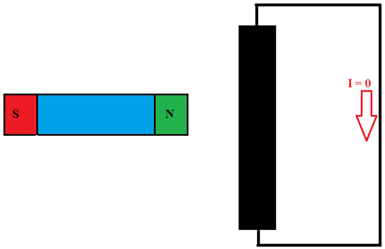
Consider a permanent magnet and a conductor is brought near to each other first.
- Then the conductor is short-circuited at both ends using a wire as shown in the figure.
- In this case, there will be no current flow in the conductor or the loop because the magnetic field cutting the loop is stationary and as mentioned in the law, only a varying or changing magnetic field can force current in the loop.
- So in the first case of the stationary magnetic field, there will be zero flow in the conductor loop.
Now consider if the magnet is moving back and forth like a pendulum then the magnetic field cutting the loop keeps changing. Since there is a varying magnetic field present in this case, Faraday's laws will come to play and thereby we can see a current flow in the conductor loop.
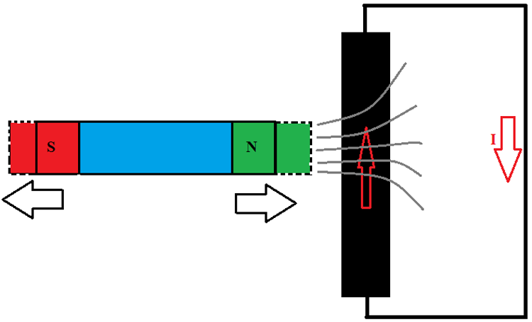
As you can see in the figure, after the magnet moves back and forth we get to see a current ‘I’ flowing through the conductor and the closed-loop.
Now let us remove the permanent battery to replace it with other varying magnetic field sources like below.
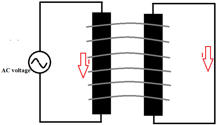
- Now an Alternating voltage source and a conductor are used to generate a varying magnetic field.
- After the conductor loop brought near to the magnetic field range, then we can see an EMF generated across the conductor. Because of this induced EMF, we will have a current flow ‘I’.
- The magnitude of induced voltage is proportional to field strength experienced by the second loop, so the higher the magnetic field strength, the higher the current flow in the closed-loop.
Although it is possible to use a single conductor set up to understand Faraday's law. But for better practical performance using a coil on both sides is preferred.
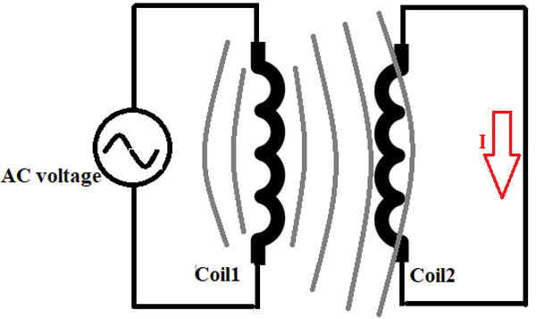
Here, an alternating current is flowing through the primary coil1 which generates the varying magnetic field around the conductor coils. And when the coil2 enters in the range of the magnetic field generated by the coil1 then an EMF voltage is generated across coil2 because of Faraday’s law of electromagnetic induction. And because of that voltage in coil2 a current ‘I’ flows through the secondary closed circuit.
Now you have to remember that both coils are suspended in the air so the medium of conduction used by the magnetic field is air. And the air has higher resistance compared to metals in the case of magnetic field conduction, so if we use a metal or ferrite core to act as a medium for electromagnetic field then we can experience electromagnetic induction more thoroughly.
So now let us replace the air medium with the iron medium for further understanding.
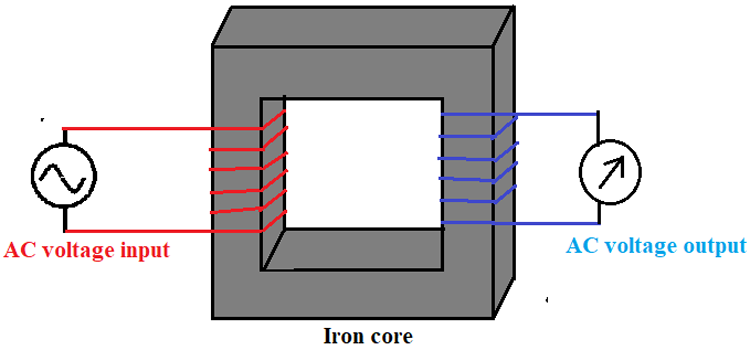
As shown in the figure we can use iron or ferrite core to reduce the magnetic flux loss during power transmission from one coil to another coil. During this time the magnetic flux leaked into the atmosphere will be considerably lesser than the time we used air medium as a core is a very good conductor of the magnetic field.
Once the field is generated by coil1 it will flow through the iron core reaching the coil2 and because of faradays law coil2 generates an EMF which will be read by the galvanometer connected across coil2.
Now if you observe carefully you will find this setup similar to a single-phase transformer. And yes every transformer present today works on the same principle.
Now let us look into the simplified construction of the three-phase transformer.
Three Phase Transformer
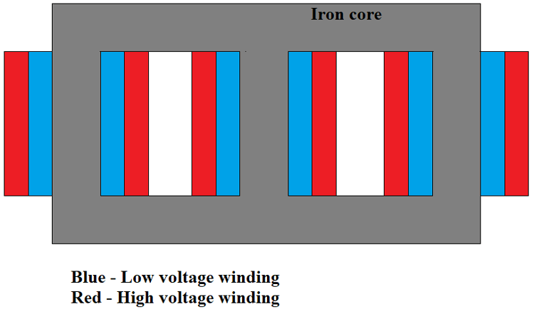
- The skeleton of the transformer is designed by staking laminated metal sheets that are used for carrying magnetic flux. In the diagram, you can see the skeleton is painted gray. The skeleton has three columns on which windings of three phases are wound.
- The lower voltage winding is wound first and is wound closer to the core while higher voltage winding is wound on top of the lower-voltage winding. Do remember, both the windings are separated by an insulation layer.
- Here each column represents one phase, so for three columns, we have three-phase winding.
- This entire setup of skeleton and winding is immersed in a sealed tank filled with industrial oil for better heat conductivity and isolation.
- After the winding, the end terminals of all six coils were brought out of the sealed tank through an HV insulator.
- The terminals are fixated at a fair distance away from each other to avoid spark jumps.
Features of Power Transformer
|
Rated Power |
3 MVA up to 200 MVA |
|
Primary Voltages typically |
11, 22, 33, 66, 90, 132, 220 kV |
|
Secondary Voltages typically |
3.3, 6.6, 11, 33, 66, 132 kV or custom specification |
|
Phases |
Single or three-phase transformers |
|
Rated frequency |
50 or 60 Hz |
|
Tapping |
On-load or off-load tap changers |
|
Temperature rise |
60/65C or custom specification |
|
Cooling type |
ONAN (oil natural air natural) or other types of cooling such as KNAN (max 33kV) on request |
|
Radiators |
Tank-mounted cooling radiator panels |
|
Vector groups |
Dyn11 or any other vector group as per IEC 60076 |
|
Voltage regulation |
Via on-load tap changer (with AVR relay as standard) |
|
HV & LV terminals |
Air cable box type (33kV max) or open bushings |
|
Installations |
Indoor or Outdoor |
|
Sound level |
As per ENATS 35 or NEMA TR1 |
Applications of Power Transfer
- The power transformer is mainly used in electric power generation and at distribution stations.
- It is also used in Isolation transformers, earthing transformers, six pulse and twelve Pulse rectifier transformers, solar PV farm transformers, wind farm transformers and in Korndörfer autotransformer starter.
- It is used for reducing power losses during electric power transmission.
- It is used for high voltage step-up and high voltage step-down.
- It is preferred during long-distance consumer cases.
- And preferred in cases where load runs at full capacity 24x7.


