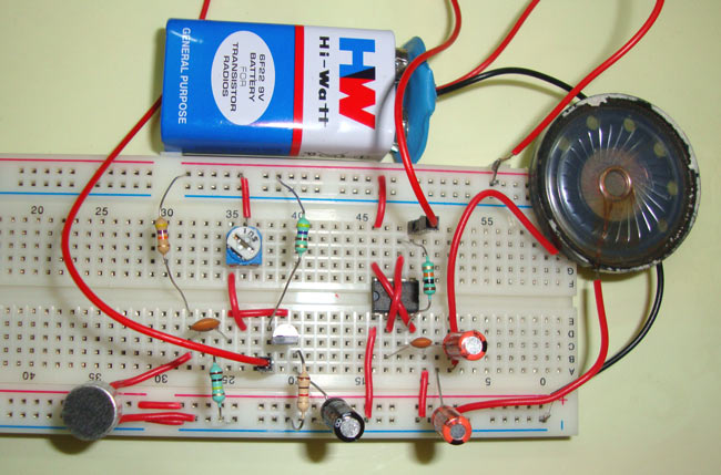
555 time IC is very powerful and versatile IC, it can be used in many forms. In this tutorial we are going to see how a 555 IC can be used as Audio Amplifier. A low power audio signal can be amplified using 555 Timer IC.
This circuit is divided into two parts: part one is Preamplifier circuit, which consist a BC547 transistor, a Condenser Mic and some resistors & capacitors. Second part consist a 8ohm speaker and a 555 timer IC, which is oscillating in Astable multivibrator mode, with approx. 66KHz frequency.
Required Components
555 Timer IC
Condenser Mic
8 Ohm Speaker
BC547 Transistor
Resistors - 470 Ohm, 1k, 10k, 47k, 100k, 680k ohm
Capacitors - 10µF, 1nF, 100nF
Battery - 9v
Breadboard and connecting wires
Circuit Diagram and Explanation
The audio amplifier circuit is shown in above diagram. Control PIN 5 of 555, has been used here which is generally kept grounded through .01uf capacitor. Control PIN 5 is the point of 2/3Vcc inside the 555 timer IC, so we can change this 2/3Vcc voltage through this PIN. And changing the voltage at this PIN change the width of output pulse, irrespective of value of RC components in 555 timer circuit. It follows the same principal of Pulse Width Modulation (PWM) to modulate the output wave. We have used this functionality of Control PIN in this circuit.
Speaker does not respond to high frequency, so when there is no voltage at control PIN 5, speaker doesn’t produce any sound. When we create some sound near Condenser Mic, that sound is converted into electric signal by the Transistor, and this electric signal is fed to the control PIN 5 of 555 IC. The output pulse at PIN 3 modulate due to this voltage at control PIN, and speaker detects this DC component of Output pulse and produce sound. Basically when there is voltage at PIN 5, width of the output PULSE increases for a moment and that is detected by Speaker.
Resistor R1 is used for biasing of condenser Mic and R2 and R3 is used to provide proper biasing to transistor. We can test this circuit by blowing some air from mouth towards the Mic, the speaker will generate sound accordingly, as I have done in the Video.
Comments
Nice work, what do i need to
Nice work, what do i need to produce a 5watts audio amplifier.
Capacitors 1nf & 100nf not
Capacitors 1nf & 100nf not avialable.
What we can do???!!!
I also had the same problem,
I also had the same problem, i did know what to do. But i hope Google can give us clarity!
Amp repair
How can i convert sound ic when the original one is burnt what are the things needed for the covertion
How would I change this
How would I change this circuit if I wished to implement it with a 3.5mm audio jack instead of the condenser mic?
Check this circuit: Audio
Check this circuit: Audio amplifier using 3.5mm audio jack
audio jack
Just remove the mic and connect right and left wires together for audio in wire and gnd to another wire thats it
How good is the sound quality
How good is the sound quality of this circuit?
What will happen if the
What will happen if the Speakers have more that 8ohms???
Is it possible to use 8ohms 5
Is it possible to use 8ohms 5 inch speaker ( more watts) in the above circuit? If not means what modification I have to do in above circuit to use bigger speaker?
And I want to use this circuit for long distance. Example, person-1 should hear clearly person-2 talking. Distance between two persons is 20-30 meters. What changes I have to for that?
does it amplify my voice when
does it amplify my voice when I speak near the mic ?
Do you know DC part has been
Do you know DC part has been stopped by C4 capacitor above speaker.its AC that's going into speaker.
--from beginner voice.(correct me if I am wrong.)
Guys,when I connected the
Guys,when I connected the circuit as given in the diagram a beeep... sound is being heard,though the input is being amplified. Can you tell me why this is happening????????How to stop this unwanted beep sound.
circuit diagram
Pin 7 is not connected so how does the capacitor discharge? I did not understand anyone, please.
Good morning
Please I was unable to get R2=680k resistor. Is there any alternative
headphone jack instead if mic?
Can you put a headphone jack instead of a mic without changing anything else, i would think you could but please someone let us know if it would be that easy or if you would have to change alot


this is a good project