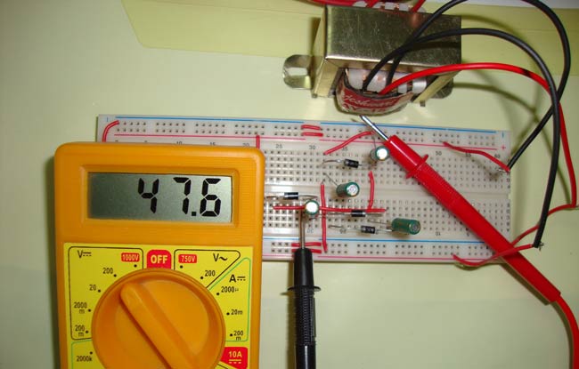
Voltage Multipliers are the circuits where we get very high DC voltage from the Low AC voltage supply, a voltage multiplier circuit generates voltage in multiple of peak input voltage of AC, like if the peak voltage of AC voltage is 5 volt, we will get 15 volt DC at the output, in case of Voltage Tripler circuit. Multimeter only reads the RMS (root mean voltage) value of AC voltage, we need to multiply RMS value to 1.414 (root 2), to get the Peak value.
Generally transformers are there to step-up the voltage, but sometimes transformers are not feasible because of their size and cost. Voltage multiplier circuits can be built using few diodes and capacitors, hence they are low cost and very effective in comparison with Transformers. Voltage multiplier circuits are quite similar to rectifier circuits which are used to convert AC to DC, but voltage multiplier circuits not only convert AC to DC but can also generate very HIGH DC voltage.
These circuits are very useful where High DC voltage needs to be generated with Low AC voltage and low current is required, like in microwave ovens, CRT (Cathode ray tubes) monitors in TV and computers. CRT monitor requires high DC voltage with low current.
Full wave Voltage Doubler
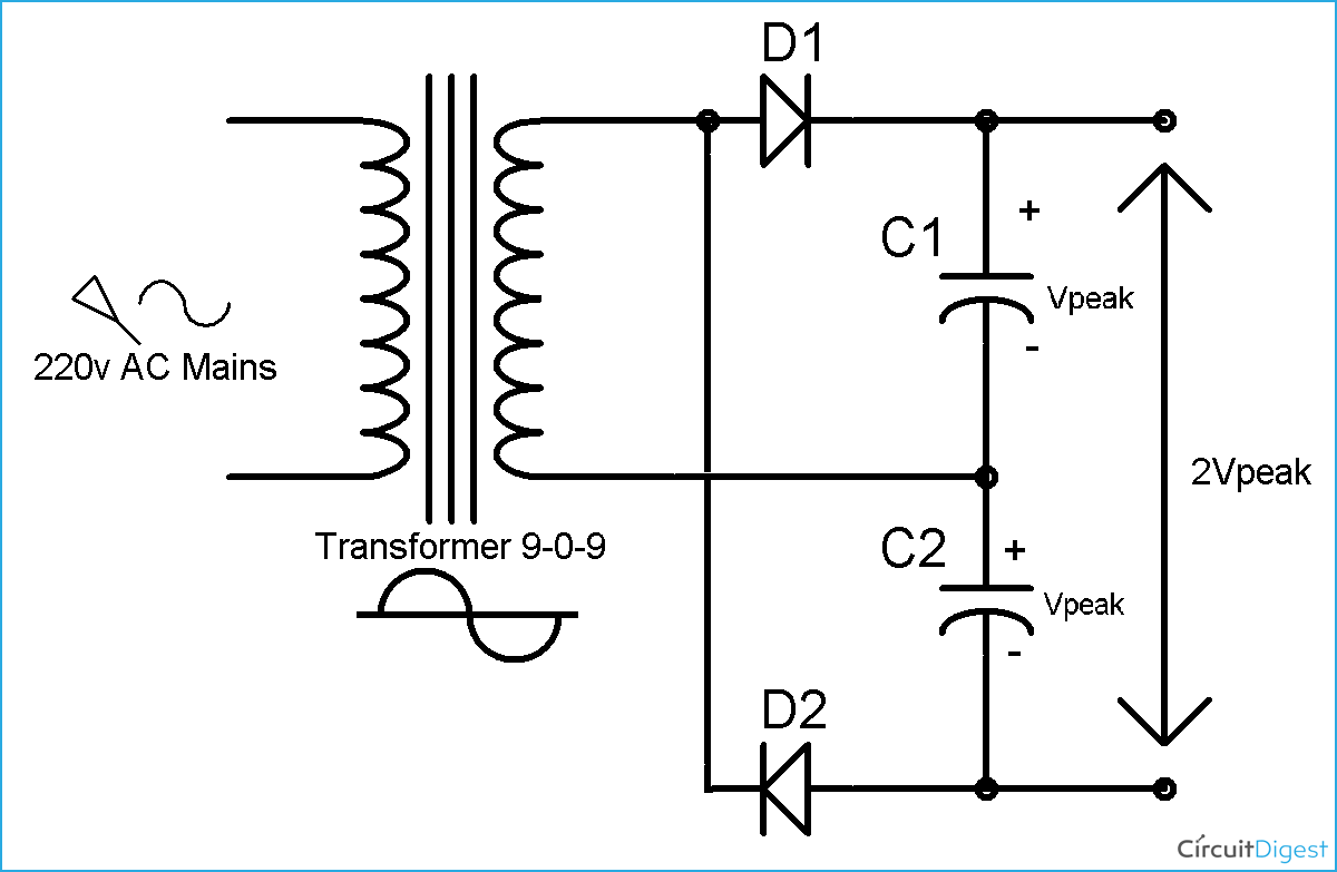
As the name indicates, input voltage gets doubled through this circuit. The operation is Full wave voltage doubler is very simple:
During the positive half cycle of Sinusoidal wave of AC, Diode D1 get forward biased and D2 get reversed biased, so capacitor C1 charges through the D1, to the peak value of sine wave (Vpeak). And during the negative half cycle of sine wave, D2 is forward biased and D1 revered biased, so capacitor C2 get charge through the D2, to Vpeak.
Now both the capacitors are charged to Vpeak so we get the 2 Vpeak (Vpeak + Vpeak), across the C1 and C2, with no Load connected. It has named after the Full wave rectifier.
Half Wave Voltage Doubler Circuit
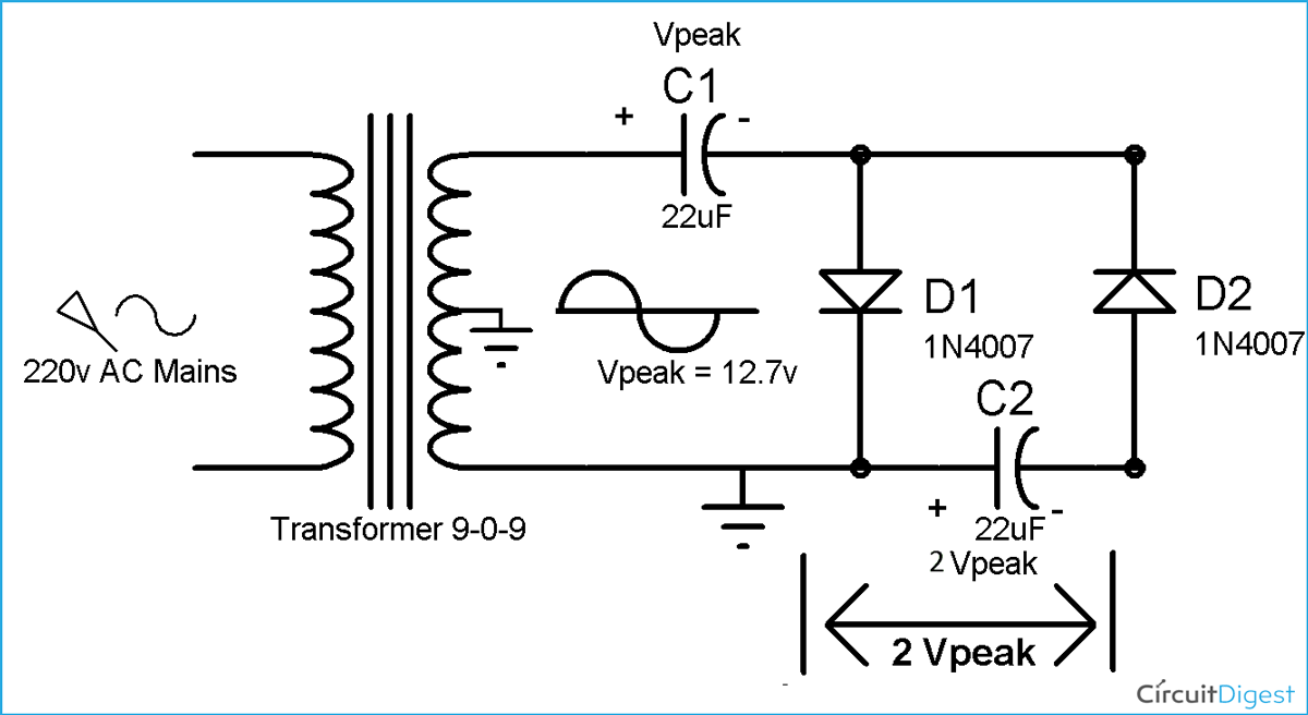
Previously we have also created Voltage Doubler circuit, with 555 timer in Astable mode and a DC source. This time we are using 220v AC and 9-0-9 transformer to step down 220v AC, so that we can demonstrate the Voltage Multiplier on breadboard.
During the first positive half cycle of Sinusoidal wave (AC), Diode D1 get forward biased and capacitor C1 get charged through the D1. Capacitor C1 get charged up to the peak voltage of AC i.e. Vpeak.
During the negative half cycle of the sine wave, Diode D2 conducts and D1 reverse biased. D1 blocks the discharging of capacitor C1. Now the capacitor C2 charge with the combined voltage of capacitor C1 (Vpeak) and the negative peak of the AC voltage that is also Vpeak. So the capacitor C2 charge up to 2Vpeak volt. Hence the voltage across capacitor C2 is two times the Vpeak of AC.
In the next positive cycle, capacitor C2 discharged into the load, if load is connected, and gets recharged in the next cycle. So we can see that it gets charged in one cycle and discharged in next cycle, so the ripple frequency is equal to the input signal frequency i.e. 50 Hz (AC Mains ).
Voltage Tripler Circuit
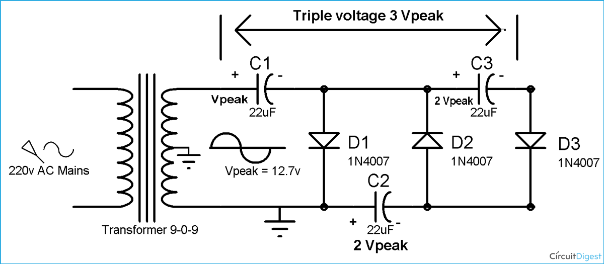
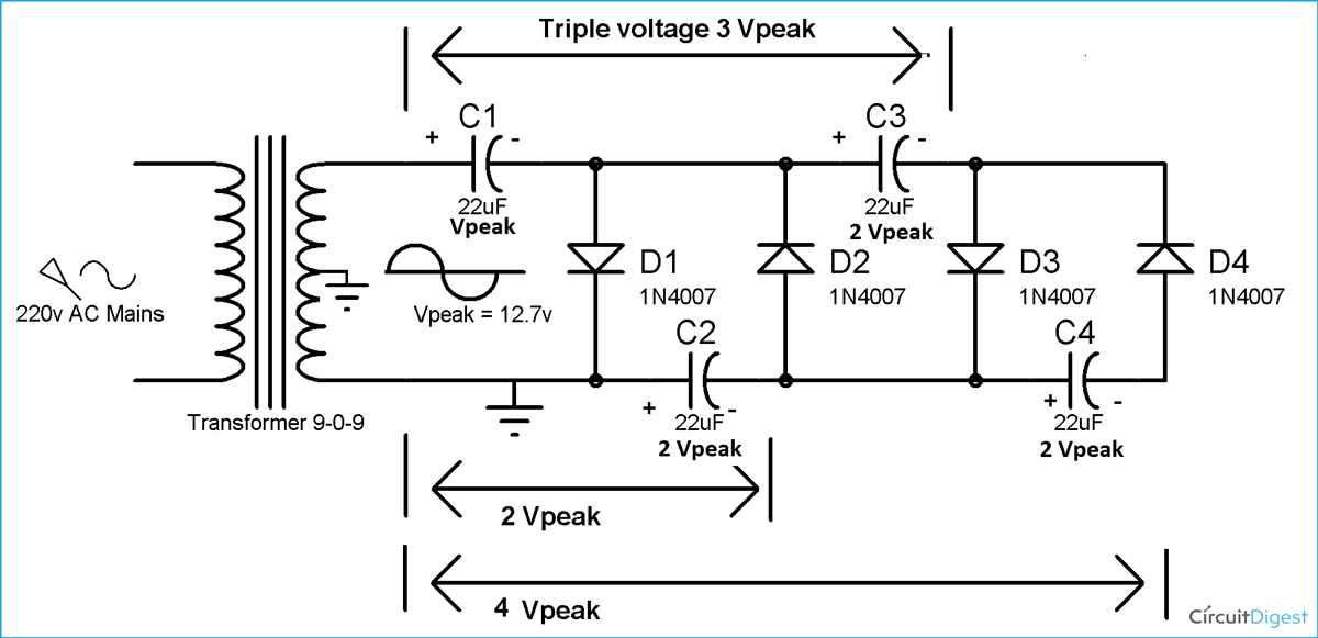
To build the voltage Tripler circuit, we just need to add 1 more Diode and capacitor to the above Half wave Voltage Doubler circuit according to the circuit diagram Below.
As we have seen in voltage doubler circuit that, in first positive half cycle capacitor C1 gets charged to Vpeak and and capacitor C2 charged to 2Vpeak in the negative half cycle.
Now during the second positive half cycle, Diode D1 and D3 conducts and D2 get reverse biased. In this way capacitor C2 charges the capacitor C3 up to the same voltage as itself, which is 2 Vpeak.
Now the capacitor C1 and C3 are in series and voltage across C1 is Vpeak and voltage across C3 is 2 Vpeak, so the voltage across the series connection of C1 and C3 is Vpeak+2Vpeak = 3 Vpeak, and we get Triple the voltage of Input Vpeak volt.
Voltage Quadruple Circuit
As we have built voltage Tripler circuit by adding one diode and capacitor in Half wave Voltage doubler circuit, again we just need to add one more diode and capacitor to Voltage Tripler circuit, to build the Voltage Quadruple circuit (4 times the input voltage).
We have seen in voltage Tripler circuit, that capacitor C1 charged to Vpeak in first positive half cycle, C2 charged to 2Vpeak in negative half cycle and C3 also charged to 2Vpeak in second positive half cycle.
Now during the second negative half cycle Diode D2 and D4 conducts, and capacitor C4 is charged to the 2Vpeak, by the capacitor C3 which is also at 2 Vpeak. And we get four times Vpeak (4Vpeak), across the capacitor C2 and C4, as both the capacitors are at 2 Vpeak.
In Voltage Multiplier circuits, practically the voltage is not exactly the multiple of the Peak voltage, resulting voltage is less than the multiples because of some voltage drop across the Diodes, so the resulting voltage would be:
Vout = Multiplier*Vpeak – voltages drop across diodes
Disadvantage of this kind of Multiplier circuits is High Ripple frequency and it’s very difficult to smooth the output, although using the large value of capacitors can help reduce rippling. And the advantage of the circuit is that we can generate very high voltage from a Low voltage power source.
We can generate much higher voltage and can get 5 times, 6 times, 7times and more, the voltage of the Peak AC voltage, by adding more diodes and capacitors. We can also generate the High negative voltage by just reversing the polarity of Diodes and Capacitors in this circuit. Theoretically we can multiply the voltage infinitely but practically it’s not possible because of capacitance of capacitors, low current, high rippling and many other factors.
Video:
Notes:
- Voltage won’t multiple instantaneously but it will increase slowly and after some time, it will set to the Thrice of input voltage.
- Voltage rating of capacitors should be at least twice the input voltage.
- The output voltage is not exactly the Multiple of Peak input voltage, it will be less than Input voltage.
all the half wave circuit
all the half wave circuit show one side of the transformer secondary shorted out. (CT and one side both grounded). Also the outputs show 2V, 3V etc should this not be 2x. 3x etc?
Also I would like to know how to select the capacitors. You have 22uF, how did you arrive at this value? Presumably, it will effect the output current but what is the formula for working this out?
What is the mathematical
What is the mathematical modelling of voltage multiplier circuit? I would like to know the expression for deciding capacitor value.
Calculation of Voltage input and Output
I'd like to add in this circuit formula the Vout = 2* Vin *1.35 -> 1.35 is the diode amplification factor?
How to get 400V for 140V transformer. Thks
Voltage doubler in AC to DC
Hello, good article I 'd like to ask you one doubt how to get 270V DC from 140V AC.
I'm stuck in that design.
Thanks



Does-it work if the input current is DC and not AC ?
I think it won't but how make a voltage doubler with DC ?
Thanks.