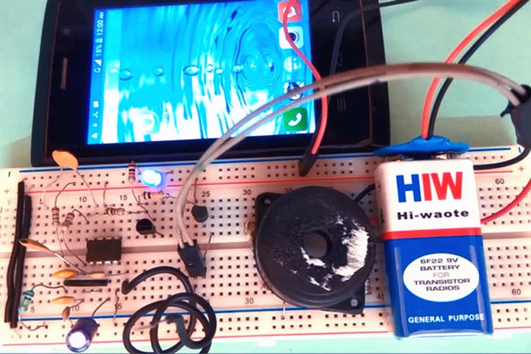
Cell Phone Detector is a circuit that can sense the presence of any activated cell-phone nearby and gives an indication of activated cell-phone near around of it. Basically Cell-phone detector is a Frequency Detector or a Current to Voltage Converter Circuit which catches frequencies about 0.8 - 3.0GHz (Mobile band frequencies). RL tuned circuit (Resistor–Inductor circuit) is not suitable for detecting the RF signals in GigaHertz range.
This Mobile Detector Circuit can detect incoming/outgoing calls, messaging, video transmission and any SMS or GPRS uses within the range of 1 meter. This circuit is very useful to detect Cell-phones at Cell-phone restricted places like Exam halls, meeting rooms, hospitals etc. It is also useful in detecting the unauthorised use or spying using hidden Cell Phone. It can detect the RF Transmission from the Mobile Phone and triggers Buzzer to produce beep sound, even if the phone is kept on Silent mode and this alarm continues beeping till the presence of RF signals.
Required Components:
- Op-Amp CA3130
- 2.2M resistor (2)
- 100K resistor (1)
- 1K resistor (3)
- 100nF capacitor (4)
- 22pF capacitor (2)
- 100uF capacitor
- Bread board
- 9 Volt Battery
- Battery Connector
- LED
- Transistor BC547
- Transistor BC557
- Connecting wires
- Buzzer
- Antenna
Circuit Explanation:
In this circuit we have used a CA3130 OP-Amp IC for detecting incoming or outgoing signal around it. Op-amp non-inverting end is connected to Vcc through 2.2M resistor and it is also connected to the ground through 100K resistor and 100uF Capacitor. Its inverting terminal is feedback from its output through a 2.2M resistor for amplify the signal. Two 100nF capacitors are connected between inverting and non-inverting terminal, working as loop antenna for the system. Two 100nF capacitors are connected in series between Pin 1 and 8 of op-amp to boost the gain of the current to voltage converter at its output pin.
Output of this op-amp is connected at the base of NPN transistor namely BC547 through a 1k resistor and a LED is connected at its emitter for indication. A buzzer is also used for sound indication by using a PNP transistor namely BC557. And a 9 volt battery is used for powering the circuit. Rests of connections are shown in the Circuit Diagram below.
Working Explanation:
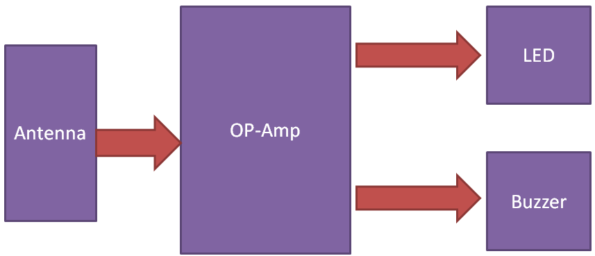
This circuit consist an op-amp with some active passive components. A LED and buzzer are used for indication of presence of cellphone. Op-amp is configured as Frequency Detector or Current to Voltage Converter and its output is connected to a LED and buzzer using NPN and PNP transistors.

Working of Mobile Detector is simple. Two 100nF capacitors (C2 and C3), in parallel, are used for detecting RF signal from Mobile Phone. These capacitors are working as loop antenna for the system. When there is any call or SMS then capacitors in parallel detect the data transmission frequencies or RF signal and output of op-amp goes high or low (fluctuating) due to generated current at the input side of op-amp. Due to these fluctuations, LED turns on and off through NPN transistor according to the signal’s frequency. Now PNP transistor is also triggered with the same frequency and buzzer starts beeping until data transmission gets finished. If you are not familiar with working of Op-amps then learn more about Op-amps here.
Comments
cell phone detetor circuit
can u please tell me?which type of antenna used for this circuit?Is it gives indication of other mobiles which is located nearby?
Two 100nF capacitors have
Two 100nF capacitors have formed the loop antenna, no other antennas are used. Learn about loop antennas.
From beginner decent voice
Please responce me>>How loop antenaa cap C2, C3 value is decided with respect of radio freq.
Basic principle
I want to know about basic principle of the circuit.
mobile detector circuit
please explain complete working of complete circuit with significance of each and every component
Compatibility
Is this device compatible with 3g frequency of mobiles
Working principle
I want to know how the Rf frequency of the signal is transformed into current in the circuit. That is for different frequencies I want to measure different current flowing in the circuit.
Antenna type
Howzit man,
After C7, that coiled-upped connector, is that what you used for your antenna?
A simple Jumper wire is used
A simple Jumper wire is used as Antenna.
please how do i increase its
please how do i increase its range?
mobile detector circuit
Can you explain more about the working principle the circuit and which antenna do we used
pls i need the complete
pls i need the complete material for this project topic
Hey I made the circuit, but
Hey I made the circuit, but it's glowing without any detection of a mobile! What do i do?
My circuit is glowing without
My circuit is glowing without any cell phone ringing
mine is as well - are there
mine is as well - are there other videos of this project? perhaps something is connected incorrectly? It also looked like the schematics vary slightly from what is pictured in the video, but hard to tell.
Mobile phone detector
Can u send the block diagram of detector without using antenna
Sir can you please send me or
Sir can you please send me or tell me what is the procedure of antenna , how it is detecting ?
Do you have a working proteus
Do you have a working proteus simulation?
Cell phone detector
Good day sir.! I acknowledged your work and how you are helping the youth by impacting on them.
Please sir can you help me with the full material of the project (cell phone detector) and circuit diagram
Thanks and remain blessed
The full project is already
The full project is already explained in this website
Please can you send me the
Please can you send me the materials and the circuit diagram. Thanks alot
mobile detector
Sir ,i riguped the ckt ...by connecting battery it starts beeping sound and also led starts glow.
Wt is the reason for this??!
About phone detector
Does it work only when the phone is used for calling? Then how to identify the phone when it is idle or doing other activities other than calling
can i get clear picture of
can i get clear picture of all the connections?
cell phone detactor
sir,i make this circuit but it does not working hence i use 24pf in C6 and C7 instead of using 22pf,i can't understand how it does not works so please tell me the reason as soon as possible,thank you
how to increase the range of
how to increase the range of detection,where it is not near by.
Can I get the calculations
Can I get the calculations for this circuit?
You said "is not suitable…
You said "is not suitable for detecting the RF signals ". I agree. Who approved this design? I think you meant "decoding" but if it cannot detect , what good is it?
Tony
EE since 1975


Hi, can I ask what type of antenna does this use? And where can I buy it? Thanks!!!