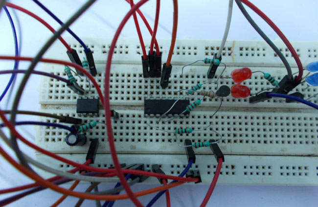
In this project we are going to design a circuit, to make a flashing light similar to that on a police car. This police light circuit is designed by 555 Timer IC and a decade counter IC. The timer here generates pulses which are fed to the 10-stage decade counter, the output of counter is so arranged to get a flashy lights as a police car.
Circuit Components
+5 to +8v supply voltage
555 IC
1KΩ, 10KΩ and 220Ω resistors (7 pieces)
10µF capacitor, 100µF capacitor (not a compulsory, connected in parallel to power).
2N3904 or 2N2222 transistor (2 pieces)
RED LED (2 pieces) and BLUE LED (2 pieces)
CD4017 IC
Circuit Diagram and Explanation
The above figure shows the circuit diagram for poice lights. The timer here generates pulses of time period 100ms approximately. So the ON time is 50ms and OFF time is 50ms. This time duration can be changed by changing the value of capacitor.
These pulses are fed to the DECADE BINARY COUNTER. Now the decade binary counter counts the number of pulses given at the clock and lets the corresponding pin output go high, for example, if the event count is 3 then Q2 pin of counter will be high and if 5 is count the pin Q4 will be high. So for every 100ms there will be a peak, with this peak the counter memory gains by one and so is the output.
Here Q0, Q2, Q4 are connected to base of one transistor and Q5, Q7, Q9 are connected to another transistor base. The first transistor drives a pair of RED LED’s and second transistor drives a set of BLUE LED’s.
As said earlier, the counter output gets incremented by one for every 100ms until the over flow. As the overflow of count takes place, the counter resets itself and starts from zero again.
Since Q0, Q2, Q4 are controls of RED pair, they will be ON for 100ms, three times as:
Q0—LED on for 100ms
Q1---LED off for 100ms, as Q1 high every other output will be LOW, and Q1 is not connected to drive RED pair.
Q2---LED on for 100ms.
Q3---LED off for 100ms.
Q4---LED on for 100ms.
By the next clock Q5 will be high and all others will be low.
Since Q5, Q7, Q9 are so connected to drive the BLUE pair. The BLUE LED’s also will be ON for 100ms and for three times.
So we have a RED pair which blinks three times and a BLUE pair which blinks there times. These two pair blinking alternatively forms the police lights.
Comments
Hi mick m.
Hi mick m.
Thanks for pointing it out. The pin 12 of 4017 should be left free as shown in bread board. This pin is used for cascading with other IC, and has no application in this project.
Thanks!!
what to do?
what is the maximum load that the transistor can handle? how many led? and if i want to increas the number of leds to 12 red and 12 blue what should i do?


hi
in the schematic there is a connection from pin 12 to ground but on the top breadboard photo the is no
connection to pin 12 on the 4017 but there is a connection to pin 16 but not on the schematic ,any info please