“The Heart of science is measurement”, and for the measurement the bridge circuits are used to find all kind of electrical and electronics parameter. We have studied about several bridges in Electrical and Electronics Measurement and Instrumentation. The below table shows different bridges with their uses:
| S.No. | Name of Bridge | Parameter to be determine |
| 1. | Wheatstone | measure an unknown resistance |
| 2. | Anderson | measure the self-inductance of the coil |
| 3. | De-sauty | measuring very small value of Capacitance |
| 4. | Maxwell | measure an unknown inductance |
| 5. | Kelvin | used to measure unknown electrical resistors below 1 ohm. |
| 6. | Wein | measurement of capacitance in terms of resistance and frequency |
| 7. | Hay | measurement of unknown inductor of high value |
Here, we are going to talk about Wheatstone bridge used for measurement of unknown resistance. Now-a-days digital multimeter helps in measuring the resistance in a simple way. But the advantage of Wheatstone bridge over this is to provide the measurement of very low values of resistance in the range of milli-ohms.
Wheatstone bridge
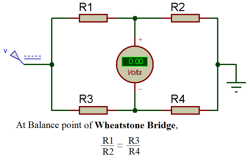
Samuel Hunter Christie invented the Wheatstone bridge in 1833 and this bridge was improved and popularized by Sir Charles Wheatstone in 1843. The Wheatstone bridge is the interconnection of four resistances forming a bridge. The four resistance in circuit are referred as arms of bridge. The bridge is used for finding the value of an unknown resistance connected with two known resistor, one variable resistor and a galvanometer. To find the value of unknown resistance the deflection on galvanometer made to zero by adjusting the variable resistor. This point is known as balance point of Wheatstone bridge.

Derivation
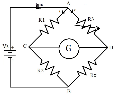
As we can see in figure, R1 and R2 are known resistor. R3 is variable resistor and Rx is unknown resistance. The bridge is connected with the DC source (battery).
Now if Bridge is in the balanced condition then there should be no current flowing through galvanometer and the same current I1 will flow thorough R1 and R2. Same goes for R3 and Rx, means current flow(I2) thorough R3 and Rx will remain same. So below are the calculations to find out unknown resistance value when bridge is in the Balanced condition (no current flow between point C and D).
V = IR (by ohm's law)
VR1 = I1 * R1         ... equation (1)
VR2 = I1 * R2         ... equation (2)
VR3 = I2 * R3         ... equation (3)
VRx = I2 * Rx         ... equation (4)
The voltage drop across the R1 and R3 is same and the voltage drop at R2 and R4 is also same in the balanced bridge condition.
I1 * R1 = I2 * R3      ... equation (5)
I1 * R2 = I2 * Rx      ... equation (6)
On dividing equation (5) and equation (6)
R1 / R2 = R3 / Rx
Rx = (R2 * R3) / R1
So, from here we get the value of Rx which is our unknown resistance and hence this is how Wheatstone bridge helps in measurement of an unknown resistance.
Operation
Practically, the variable resistance is adjusted till the value of current through the galvanometer becomes zero. At that point, the bridge is called as balanced Wheatstone bridge. Getting zero current through galvanometer gives high accuracy, as a minor change in variable resistance can disrupt the balance condition.
As shown in the figure, there are four resistance in the bridge R1, R2, R3 and Rx. Where R1 and R2 are the unknown resistor, R3 is the variable resistance and Rx is the unknown resistance. If the ratio of known resistors is equal to the ratio of adjusted variable resistance and unknown resistance, in that condition no current will flow through the galvanometer.
At balanced condition,
R1 / R2 = R3 / Rx
Now, at this point we are having the value of R1, R2 and R3 so it’s easy to find the value of Rx from the above formula.
From the above condition,
Rx = R2 * R3 / R1
Hence, the value of unknown resistance is calculated through this formula, given that current through Galvanometer is Zero.
So we need to adjust the potentiometer till the point when voltage at C and D will be equal, in that condition current through point C and D will be zero and the Galvanometer reading will be Zero, in that particular position Wheatstone Bridge will be called in Balanced condition. This complete operation is explained in the Video Given below:
Example
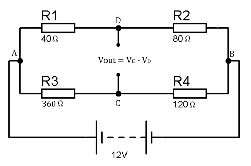
Let us take an example for understanding the concept of Wheatstone bridge, as we take an unbalanced bridge to calculate the appropriate value for Rx (unknown resistance) to balance the bridge. As we know if the difference of voltage drop across point C and D is zero then the bridge is in balance condition.

According to the circuit diagram,
For the first arm ADB,
Vc = {R2 / (R1 + R2)}* Vs
On putting the values in the above formula,
Vc = {80 / (40 + 80)}* 12 = 8 volts
For the second arm ACB,
Vd = {R4 / (R3 + R4)}* Vs
Vd = {120 /(360+ 120)}*12 = 3 volts
So, the voltage difference between point C and D is:
Vout = Vc - Vd = 8 - 3 = 5 volts
If the difference of voltage drop across C and D is positive or negative (positive or negative shows the direction of unbalance), it shows that the bridge is unbalanced and for making it balance we need a different value of resistance in replacement of R4.
The value of resistor R4 required for balance the circuit is:
R4 = (R2 * R3) / R1 (condition of balance bridge)
R4 = 80 * 360 / 40
R4 = 720 ohm
Hence, the value of R4 required to balance the bridge is 720 Ω, because if the bridge is balance the difference of voltage drop across C and D is zero and if you can use a resistor of 720 Ω the voltage difference will be zero.
Applications
- Mainly used in measuring of very low value of unknown resistance having range of milli-ohms.
- If using a varistor with Wheatstone bridge we can also identifies the value of some parameters like capacitance, inductance and impedance.
- By using Wheatstone bridge with operational amplifier it helps in measuring different parameters like temperature, strain, light etc.
We can use multimeter to
We can use multimeter to measure resistance? Then what is the need for Wheatstone bridge??
for the measurement of very
for the measurement of very low value of resistance (having range in milli-ohms)
Good explanation , so hard to
Good explanation , so hard to find this info on other sites. but was wondering what sim software you are using as i would like to duplicate this circuit?.


Thanks to the author for sharing his knowledge. I was looking for this kind of info and I found it here.