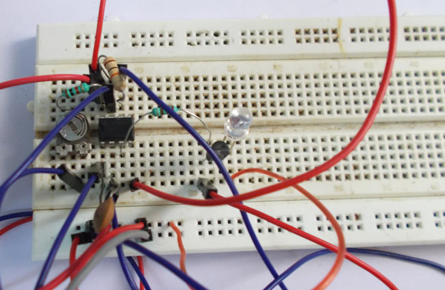
TV remote control is a commonly used device in our everyday life. Would you like to surprise your family members or friends by making this fun circuit namely "TV remote jammer circuit"? Yes you can use this circuit to stop the working of your TV remote and nobody would have a clue about why that stopped working. This project we have designed is a simple circuit, which blocks the communication established between TV and remote control. (Also check this IR remote control tester circuit)
The communication between TV and remote control is IR (Infra Red) communication. So basically this circuit is a IR jammer circuit. As shown in below image the remote consists of an IR (Infrared) LED, which blinks every time a button is pressed.
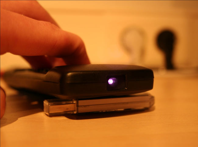
The TV consists of an IR receiver which receives these blinking pulses and decodes them for appropriate response. These IR pulses by remote control can not be detected by human eye. These pulses can be captured by a camera, as camera can pick up these pulses.
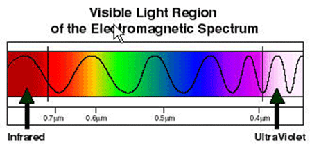
As shown in figure, the IR communication established between TV and remote uses a wave length just above visible RED color.
Circuit Components
- +5v power supply
- IR (Infra Red) LED (2 pieces)
- 555 Timer IC
- 220Ω, 1KΩ and10KΩ resistors
- 2N2222 transistor
- 100KΩ preset or pot
- 10nF or 22nF capacitor
Circuit Diagram and Explanation
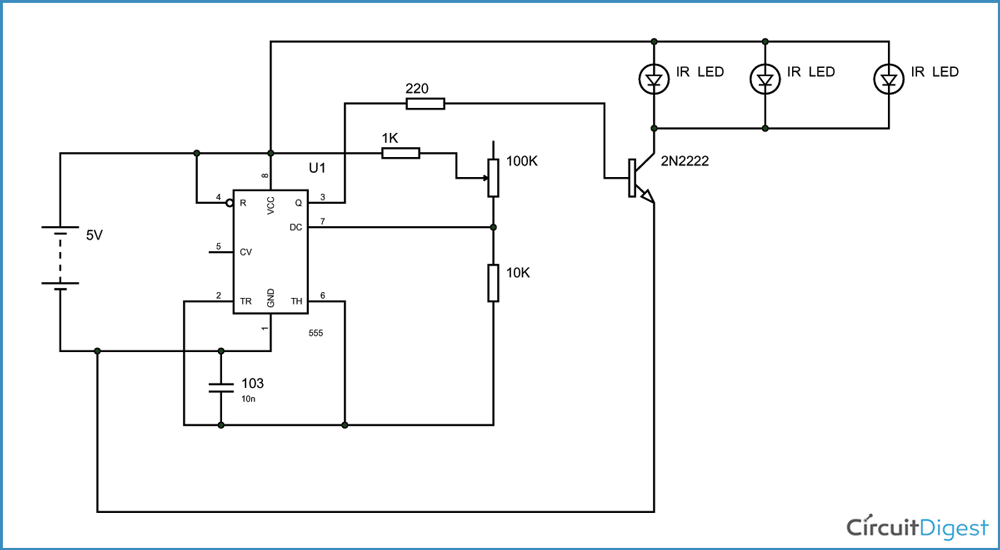
A TV Remote Control Signal Jammer Circuit Diagram is shown above. The communication established here is of frequency 32.5 KHz. That means the IR LED blinks at a rate of 32 KHz. Because this is too fast for a camera to pick, It picks up continuous turned on pulse.
As shown in the below figure, the transmitter or remote blinks at 38 KHz whenever it need to send ONE or HIGH signal. The pulses when passed through decoders or filters at the receiving end (In this case, a TV) we get a complete ONE logic as shown in second graph of figure.
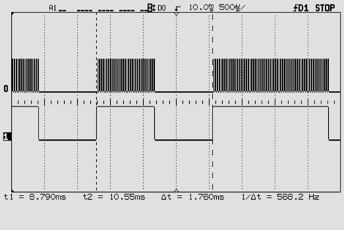
So every time a button is pressed the remote sends out 38 KHz frequency IR pulses with regular intervals. These intervals differ with every button pressed. Because of these different intervals the receiver gets the correct information regarding the user requirement and acts accordingly.
Now how we are going to stop the communication is the tricky part! We are going to design a circuit which sends the pulses continuously. Because of these continuous pulses the receiver cannot pick up the intervals send by the TV remote control.
Because of the continuous pulses by the TV remote signal jammer circuit the intervals of the remote are overlapped and the receiver reads ONE always. Simply speaking we are going to induce a lot of noise into the IR signal, for the receiver to completely read error all the time.
So, 555 IC timer here is designed to generate 38 KHz square wave. This square wave when connected to IR LED, the LED generates pulses at the same frequency. The potentiometer in the circuit must be adjusted to get the correct frequency.
The timer output here is given to transistor to drive a couple or more IR LED’s. The pulses by jammer LED’s here overlap the communication intervals between remote and TV. So the TV reads always HIGH or ONE when the jammer is ON. Because of this, there will be no communication between the transmitter and receiver. This way we can block the TV remote communication.
Comments
The 555 should be able to
The 555 should be able to take 9V, most are rated at ~18V, but check the datasheet of your version to be sure.
To keep the LED in one piece you might have to switch out a few resistors for different values.
how i can pogress range of
how i can pogress range of this jammer ? Have a ans
you can check out this
you can check out this project-long range ir sensor by circuitdigest
i think you use a push button
i think you use a push button or a slide switch
working isssue
I make it but it is not working ,it produce IR signal but not jammed tv signal
How are you sure that it is
How are you sure that it is producing IR signal ?
You can check this using a
You can check this using a cell phone camera. Run the circuit and look the LED using camera
please check the frequency of
please check the frequency of the circuit,if it not 38Khz or as close than this circuit would not jam the tv remote so try this and than reply me thank you
sir,can i used this circuit
sir,can i used this circuit as a ir transmitter circuit?



can i use 9v battery instead of 5v power supply?