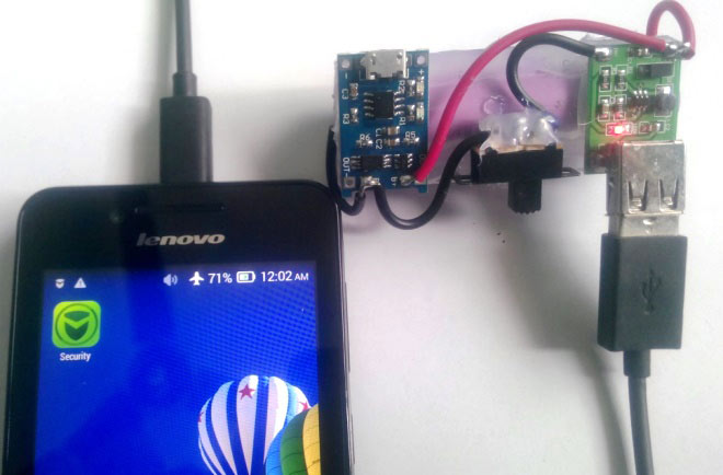
The features of the digital products are growing enormously which triggers the frequent usage of smart phones in several applications. Thus the battery backup time is getting decreased. It will be fun to build a Power Bank for Mobile Phone as spare charging source for emergency purpose which is also portable. In this article we will discover how to make a power bank with a super simple power bank circuit diagram.
The important factor to be considered while working with lithium batteries is protection circuits and quality of batteries. But, when this comes to 18650 cells the risk factor is less compared with pouch batteries. Good protection is offered by few readymade modules available in market.
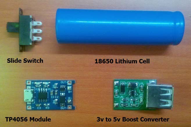
Components required for Power Bank Circuit:
- 18650 Lithium cell
- TP4056 Module with battery protection circuit
- 3V to 5V boost converter with 1A current control
- Slide switch
Power Bank Circuit Diagram:
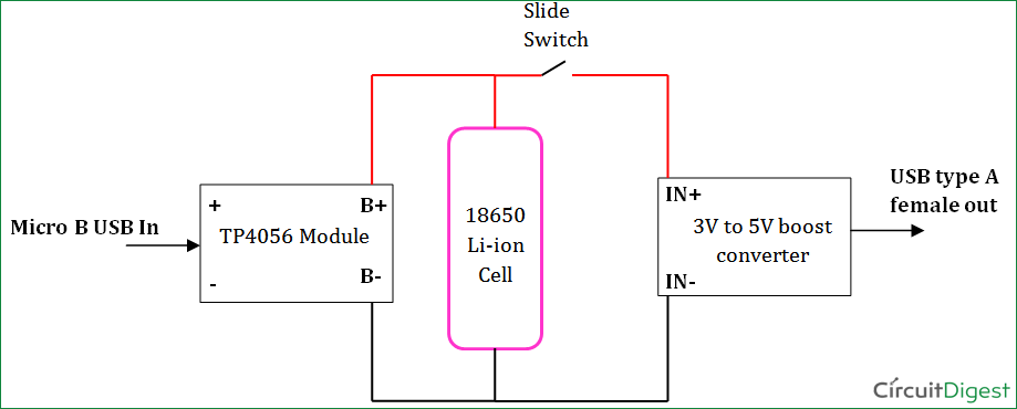
Below is the circuit diagram for our power bank. As we can see its fairly easy to make a power bank with li-ion battery, TP4056 module and a boost converter.
18650 Lithium Cell:
18650 lithium cell is the important part of this power bank circuit. The term 18650 cell is due to the cell dimension, it is cylindrical in shape with 18mm diameter and height of 65mm. Also these cells are available in different capacities corresponding to applications. They are rechargeable cells with 3.7v output.
The method of charging a single lithium ion cell requires two stage,
- Constant current (CC)
- Constant voltage (CV)
During CC the charger should supply constant current with increasing voltage till the voltage limit. Next a voltage equal to maximum limit of cell should be applied during which the current declines steadily to the lower threshold current (i.e., 3% of constant current). All these operation is carried out by the TP4056 module which is highly reliable and affordable choice.
TP4056A Module:
This is a low cost charging solution to charge any type of single lithium ion battery. Mobile batteries, 18650 NMC cells, Lithium pouch batteries, etc. The micro B Receptacle and easy adjustable 1A output current control makes it reliable choice to charge any low capacity batteries. It can be connected to any wall socket based mobile charger or any sort of USB to micro B cable. It is made of an integrated PMOS load switch architecture, hence reducing overall additional components.
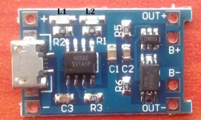
The module also has two indications, Red color LED (L1) to indicate the ongoing charging condition. Blue color LED (L2) indicates the completion of charging. This module can operate at high ambient temperature since the thermal feedback can regulate the charge current. The charge voltage is 4.2V and current can be adjusted by changing a resistor in the module. But, the default current will be 1A when bought.
The protection circuit includes,
1. DW01x – Single cell lithium ion battery protection IC with dual MOSFET control feature. Below is a application test circuit provided in the datasheet.
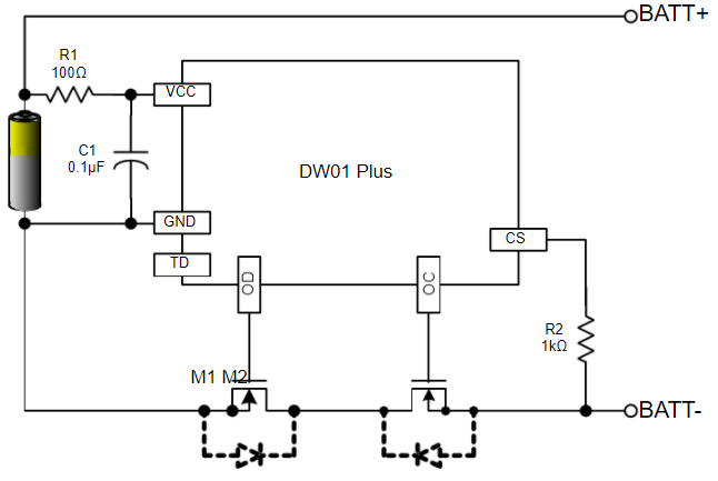
2. FS8205A – Dual N-Channel enhancement MOSFET with common drain connection. Also the drain to source resistance is low. The gate of the MOSFET is controlled through the DW01A IC.
Thus, the DW01A provides Overcharge control, Over discharge control, Overcurrent control by controlling the MOSFET through the circuit.
Micro USB 3V to 5V Boost Converter:
Lithium battery is only providing 3.7 volt here but we need 5v to charge the Cellphone, so we have used 3v to 5v boost converter module here. This boost converter module has high efficiency of upto 92% and integrated over current protection. The topology used inside is Non-isolated step-up converter which operates at a switch frequency of 1MHz. The overall power output that can be drawn out of this module is 5W. The output voltage can be adjusted to 12V by changing a resistor in module but the maximum current will be 400mA. But by default this module is available at a rating of 5V, 1A. Under this rating the output ripple is 20mV pk-pk. The module also has USB type-A female receptacle which is universal. Any USB power cable can be used as interface. The operating temperature of the module is -40°C to +85°C. It also has an LED indication to indicate the presence of supply from battery source. The Red color Led indicates the presence of power supply across the terminals.
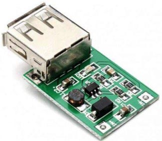
We previously used the same module in Solar Mobile Phone Charger Circuit.
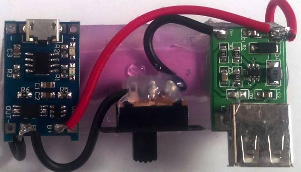
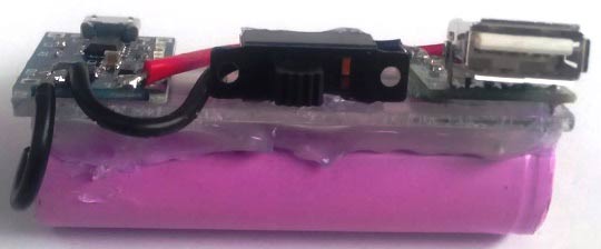
The modules were connected and fixed to a plastic plate using hot glue.
Charging the Power Bank Circuit:
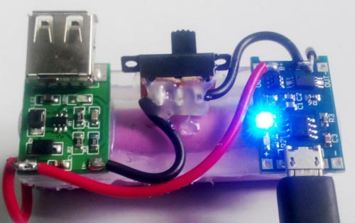
Red color LED indicates the battery charging in this power bank circuit,
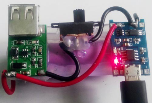
Blue color LED indicates the charge complete,
Charging the Mobile Phone with this Power Bank:
1. Connect the USB to micro B cable to the output of boost converter.
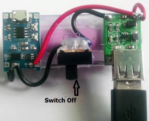
2. Turn the slide switch ON.
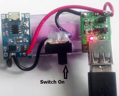
3. The mobile phones battery starts to get charge from the power bank

So this is how you can easily make Power Bank Circuit for charging your Smart Phones. Below you can find the video which demonstrates how to build 18650 Lithium Cell based power bank circuit.
Comments
To increase capacity number
To increase capacity number of lithium cells can be increased in parallel.
When using the same module arrangement the charging time increases
equally to the capacity, Eg: 10000mAh takes about 10 hours to charge from
empty to full. But, there is no other problem in using in that way. Ensure the
cells that are connected in parallel are of same capacity (For eg : 3.6V, 2200mAh).
So there is no need to be
So there is no need to be worried about balance charging? and where would we be able to connect a higher input voltage if the batteries allowed for it, or would we just create a whole new circuit leading to the positive and negative ends of the batteries in parallel in order to charge at a higher voltage?
how much time does it take to
how much time does it take to charge cell phone>?
how can I increase the current to 2A
how can I increase the current to 2A?
I don't think increasing the
I don't think increasing the current is an easy task here. You will need major modifications
What about connecting 2 (or
What about connecting 2 (or more) TP4056 in parallel? Of course, thinking in a power source wich can handle, say, 2A (or more)... Could it work?
This module is designed to
This module is designed to charge a 18650 cell whose full charge voltage is 4.2V. Also the charging current of these cells are rated less than 1A. So why do you need a 2A charger? A charging current of 2A or more could easily kill a 18650 cell..
The idea of using two modules in parallel might actually work though
Where to buy the parts?
Anyway you can give me a website i could purchase the parts from?
this circuit does not have an
this circuit does not have an over-discharge protection? because the booster is fixed to the battery, hence the TP4056A can't prevent over-discharge?
This circuit does have a over
This circuit does have a over-discharge protection.
The booster is connected to the output of the TP4056A module. If the booster drains too much current from the battery the TP4056 will prevent it from doing so.
There is no over-discharge
There is no over-discharge protection. The booster is connected in parallel to the battery and TP4056, thus even if the TP module was powered on it would have no control over the discharge from the booster. To fix this you need a discharge protection IC in series with the booster and battery.
Can we use old mobile battery
Can we use old mobile battery/s in place of 18650 cell
Good idea and it would most
Good idea and it would most likely work I guess. Why not give it a try!!
about 18650 lithium cell
which type of battery used protected/unprotected lithium celll????
The battery used here 18650
The battery used here 18650 lithium cells.. and they do not come with protection circuit
A simple query
My power bank is crashed when i connect the bettery terminal on the circuit board the blue light begins to gow with a sound "geeeeeeeeeeeeeeee............"
Boost converter
Can anyone tell me the design for boost converter of 19V & 3amp o/p
Mistakes
The circuit you give is different from the PCB. On the circuit you have the switch between the 2 pluses, on the PCB you have it between the 2 minuses. You do not give good explanations how to connect the switch and you do not show the connections well on the PCB pictures.
The switch is used only to
The switch is used only to break or make the connection. It can either be present on the positive rail or on the negative rail. However having it on the negative rails is a bit more advantages
no deep discharge protection
i don`t see a deep discharge protection. if it is the step-up booster i think it is.
It discharge your battery to almost a 0,5 volts lithium battery`s dont like that and wil posibley be dead or get dangerous after it, becouse the chemestry inside the battery wil get unstable. inside your phone te battery is monitored by a bms battery monitoring system en wil never !!!! be fulli dicharged.
so my 2 cents, get a undervoltage protection at a rc hobby shop for example.
Over discharge protection is present
No mike you don't have to worry about that. The charging module also has a protection feature in it. It will not allow the battery to drain below 3.2V.
3 old laptop batteries and tp4056 board which usb board to use?
I have connected (3) old laptop batteries serially with tp-4056 board for charging the batteries but how to charge the mobile from the batteries what usb board to use? Ampere handling ??? Plz. help.
No you should not do it.
No you should not do it.
The TP-4056 is meant to charge only one battery at a time. If you have connected the batteries in series and then have connected to the module, then you the voltage off all the three batteries would have added up and thus damaged your module
Please guide me create power bank tp4056 & laptops batteries..
I bought the 4056 module Need to reduce the ampere and increase the voltage to charge up the mobile, how to do need your advise.
Booster board
Do you have the circuit diagram for the booster chip?
dis advantagrs
what are disadvantages increasing the number of cells for 2000 mah powerbank circuit ?
The circuit is heating
Thank you for the instructions. I made it. but the boost converter is heated when the mobile phone is charging.Is there any solution to reduce the heat. Or , does the guage of wires matter for this situation as the wires can't bear the current?
pls sir out four cell inside
pls sir out four cell inside d power banks i add one cell to make it five i discover that d pannel is hoting
How can I make a 12V 18000mAh
How can I make a 12V 18000mAh battery bank?? Is it possible?? And how I'll connect it to my load?? thanks
You are asking for a 12V 18Ah
You are asking for a 12V 18Ah battery.
It can be found in your computer UPS and yes it can be used as a power bank.
If you want to make it small you should use lithium which is not a beginner friendly
Doubt about pwerbank
When we charging the power bank battery we need to ON the switch?
It depends on the Adapter
It depends on the Adapter rating . If the adapter is rated for 1A that is 1000mA then it will take (2000mah/10000mA) two hours to charge it
Compact Power banks for Smartphones.
Can we design & construct Compact Power banks for Smartphones similar to a Flash Drive?
The electrical circuit has to be further modified to achieve compactness with the Battery construction.
Thanks & Regards,
Prashant S Akerkar
Switch and protection
Excellent tutorial. Much appreciated! Hopefully you are still checking this. I was actually in the process of making one of these when I cam across this. I had two manin questions,
#1. is the switch necessary? Is the purpose to keep from the phone battery reversing and draining into the power bank? If not, and if it cen be made without the switch is there something in the circut that is preventing the reverse draining?
#2. If I already have a protection circut on a lipo battery, is the 4056A necessary? or could I use a simple 5 pin micro usb board with no circuitry?
Thansk!
Brian Martin
power bank for smart phone
the batteries are well charged and when the load charging switch is switched on , after few seconds the out put at the USB falls to zero.
This happens on ' no load ' and also 'on load ' condition.
please suggest a solution.



How can you increase the powerbank's capacity, like for example bout 10000mAh?
Would there be any changes with regards to the module used?